Percutaneous posterior lateral in-situ cage

a percutaneous and in-situ cage technology, applied in the field of percutaneous posterior lateral in-situ cage, can solve the problems of increasing the morbidity of anterior in-situ cage placement, large dissection, plif and tlif approaches,

Inactive Publication Date: 2011-10-25
CTL MEDICAL CORP
View PDF20 Cites 48 Cited by
  • Summary
  • Abstract
  • Description
  • Claims
  • Application Information

AI Technical Summary

Problems solved by technology

This can lead to pinching and irritation on the nerves, causing pain.
There are several drawbacks with existing approaches and techniques, such that further research and improved designs are desirable.
Increased morbidity of anterior in-situ cage placement is not justified when less anatomic correction of the disc space is possible.
Additionally, current PLIF and transverse lumbar interbody fusions (TLIF) cage and allograft placements require large dissections for exposure.
PLIF and TLIF approaches also weaken existing posterior elements via bony destruction resulting from the operative procedure used to access the disc space.

Method used


Image

  • Percutaneous posterior lateral in-situ cage
  • Percutaneous posterior lateral in-situ cage
  • Percutaneous posterior lateral in-situ cage

Examples


Embodiment Construction

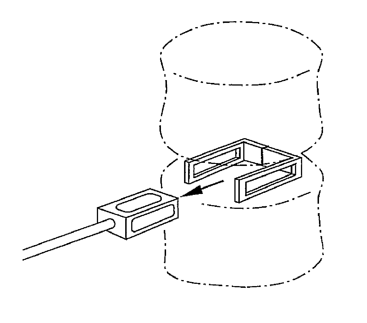
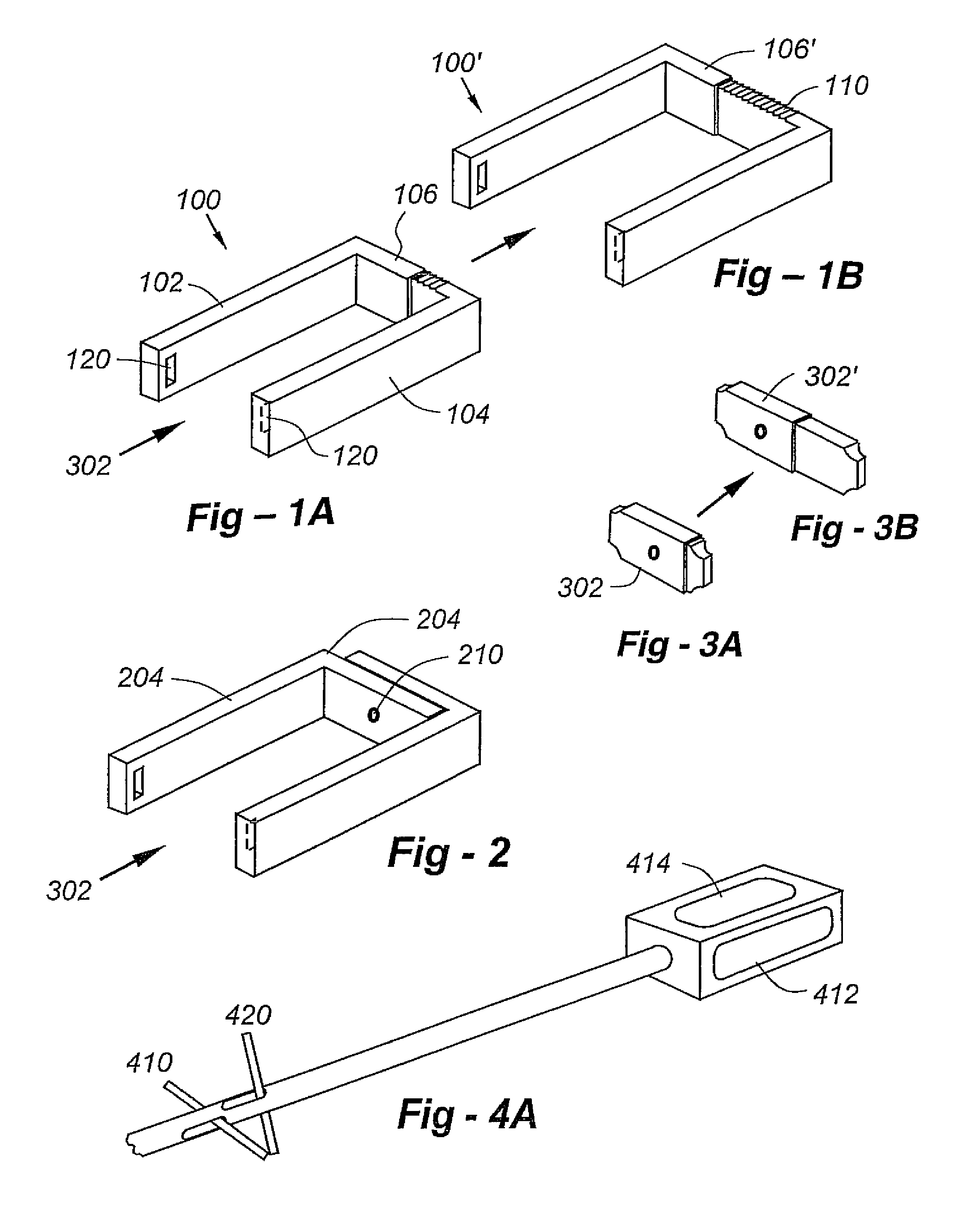
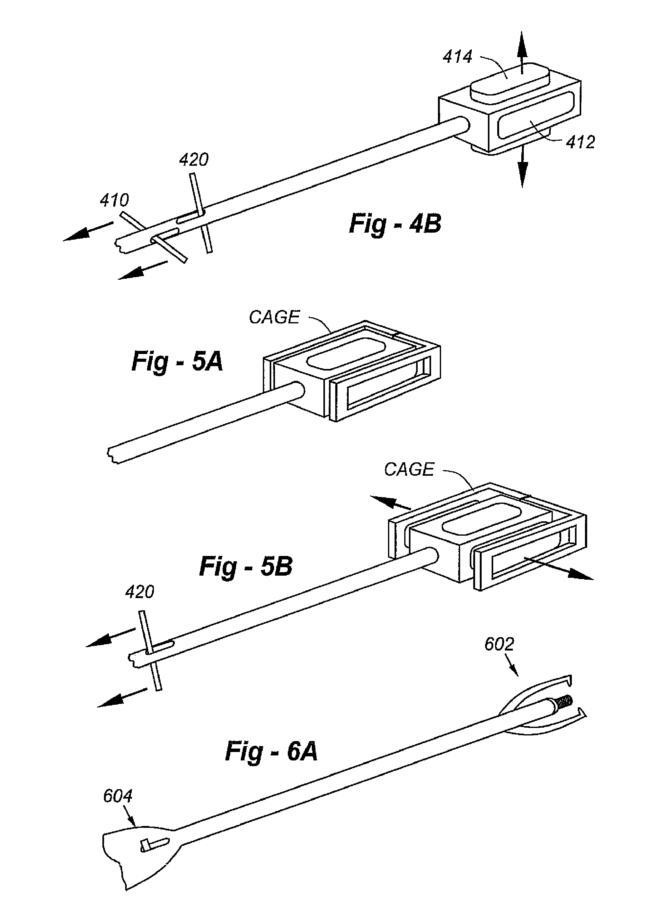
[0043]This invention resides in an expandable, locking intervertebral cage facilitating a minimally invasive percutaneous posteo-lateral approach. FIG. 9 is a perspective view drawing showing the expanded, filled cage in position between upper and lower vertebral bodies. In this description, the cage designs and novel instruments will first be introduced, followed by a detailed description of the preferred surgical procedure.

[0044]The cage is preferably radiolucent, being composed of a carbon fiber, but with one or more radiopaque markers to provide a certain degree of visualization. Full or partial metal or ceramic construction may also be used. Some or all of the walls of the cage may include superior and / or inferior surface features to enhance positioning and / or minimize back-out, and the posterior wall may be indented to prevent neurocompression. The sidewalls of the cage may further include a recessed face with nipple indents and locking fasteners. Multiple cages may provided, ...


PUM


Abstract

Implants, tools and techniques facilitate a percutaneous posterior lateral approach to the placement of an in-situ cage, and an inventive cage design to meet this objective. In terms of apparatus, the invention includes a laterally expandable cage, including a locking gate, enabling the system to be introduced into an intradiscal space through a minimally invasive percutaneous posteo-lateral approach. In addition to the cage designs, adapted to hold bone graft and / or other biologic materials, the invention includes other novel instruments, including an introducer associated with cage placement, deployment and closure.

Description

REFERENCE TO RELATED APPLICATION[0001]This application claims priority from U.S. Provisional Patent Application Ser. No. 60 / 516,209, filed Oct. 31, 2003. This application is also a continuation-in-part of U.S. patent application Ser. No. 10 / 462,498, filed Jun. 16, 2003 now U.S. Pat. No. 7,674,297, which claims priority from U.S. Provisional Patent Application Ser. No. 60 / 388,974, filed Jun. 14, 2002. The entire content of each application is incorporated herein by reference.FIELD OF THE INVENTION[0002]This invention relates generally to development of tools and techniques for percutaneous posterior lateral approach to place a modified in-situ cage.BACKGROUND OF THE INVENTION[0003]One of the most common causes of chronic back pain is degenerative disc disease. The degeneration may start after a particular injury, or many occur due to multiple injuries over time. Degeneration usually takes several years. As the vertebrae grow closer, the openings in the back of the spine where the ner...

Claims


Application Information

Patent Timeline
Patent Type & Authority Patents(United States)
IPC IPC(8): A61F2/44A61F2/00A61F2/28A61F2/30
CPCA61F2/4455A61F2/30965A61F2002/2835A61F2002/3008A61F2002/30131A61F2002/305A61F2002/30904A61F2220/0025A61F2230/0013A61F2250/0098
Inventor FALAHEE, MARK H.
Owner CTL MEDICAL CORP
Why Eureka
Try Eureka