
Rolling printing device for metal coil and rolling printing method for metal coil

A metal coil and coil technology, which is applied in the directions of printing devices, printing, printing machines, etc., can solve the problems of inability to realize continuous whole-roll substrate printing, inability to realize pattern printing, insufficient aesthetics, etc., and achieve good visual appearance and anti-counterfeiting. function, improve the shortcomings of sheet-fed flat printing, and fill in the effect of technical gaps

Inactive Publication Date: 2011-09-21
ZHUHAI SANYUAN ALUMINUM
View PDF5 Cites 6 Cited by
  • Summary
  • Abstract
  • Description
  • Claims
  • Application Information

AI Technical Summary

Problems solved by technology

The traditional printing of metal coils is generally to first cut the coiled substrate into a single piece, and then perform single-sheet flat printing. The disadvantage of this printing method is that it cannot realize continuous printing of the entire roll of substrates, and the production efficiency is low.
In addition, the traditional printing method usually can only achieve a single solid-color coating printing, and cannot realize pattern printing. This kind of coating printing effect is not beautiful enough, and cannot meet the increasingly high visual requirements of the product.

Method used


Image

  • Rolling printing device for metal coil and rolling printing method for metal coil
  • Rolling printing device for metal coil and rolling printing method for metal coil
  • Rolling printing device for metal coil and rolling printing method for metal coil

Examples


Embodiment 1

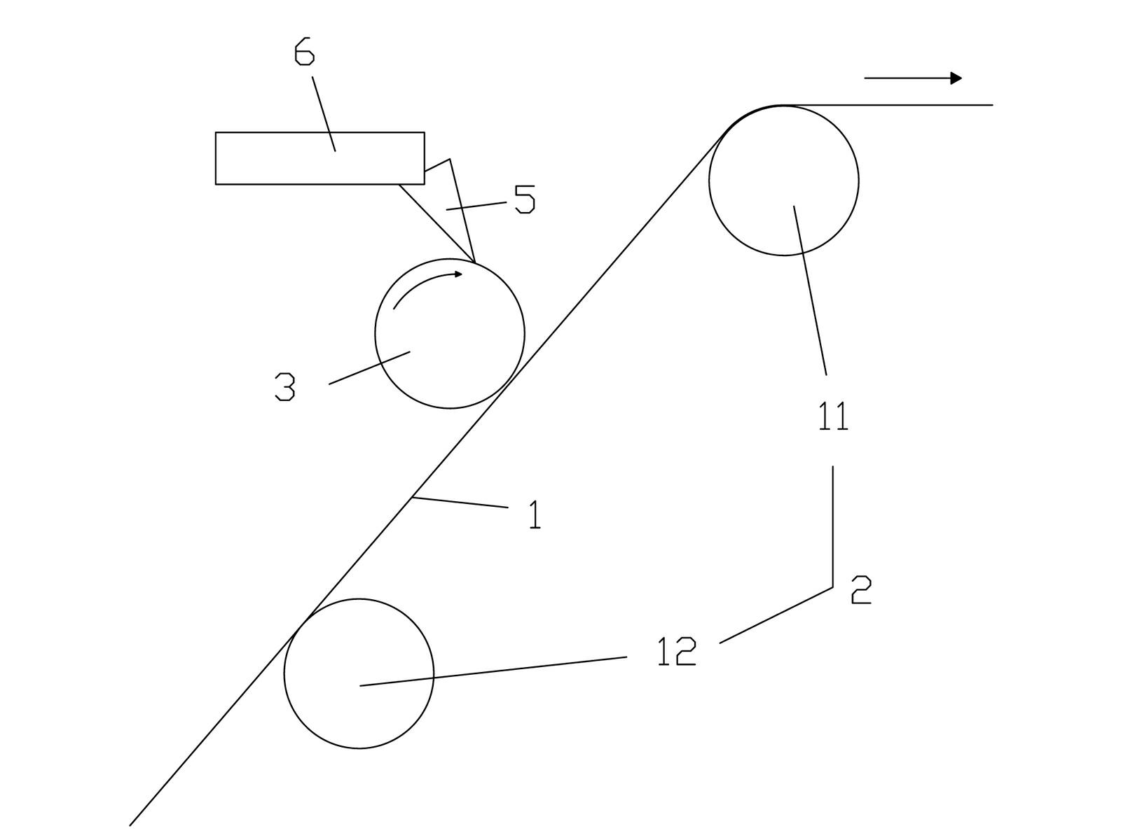
[0018] refer to figure 1 , the metal coil printing device includes: a support 2, a coil substrate 1 is arranged on the support 2, and the coil substrate 1 moves on the support 2, and the movement of the coil substrate 1 can be carried out by various common driving parts Drive implementation; rotatable printing roller 3, the surface of the printing roller 3 is engraved with printing patterns, and the surface of the printing roller 3 is abutted against the coil substrate 1; it is used to add printing material to the printing roller 3 Material filling part 4. In this embodiment, the printing material filling part 4 includes a printing material tank 6 and a scraper 5, and the printing material in the printing material tank 6 is scraped onto the printing roller 4 by the doctor blade 5. The realization of this printing material filling part 4 The method is relatively simple, and the filling effect can meet the needs of basic production. The support member 2 includes a left support...

Embodiment 2

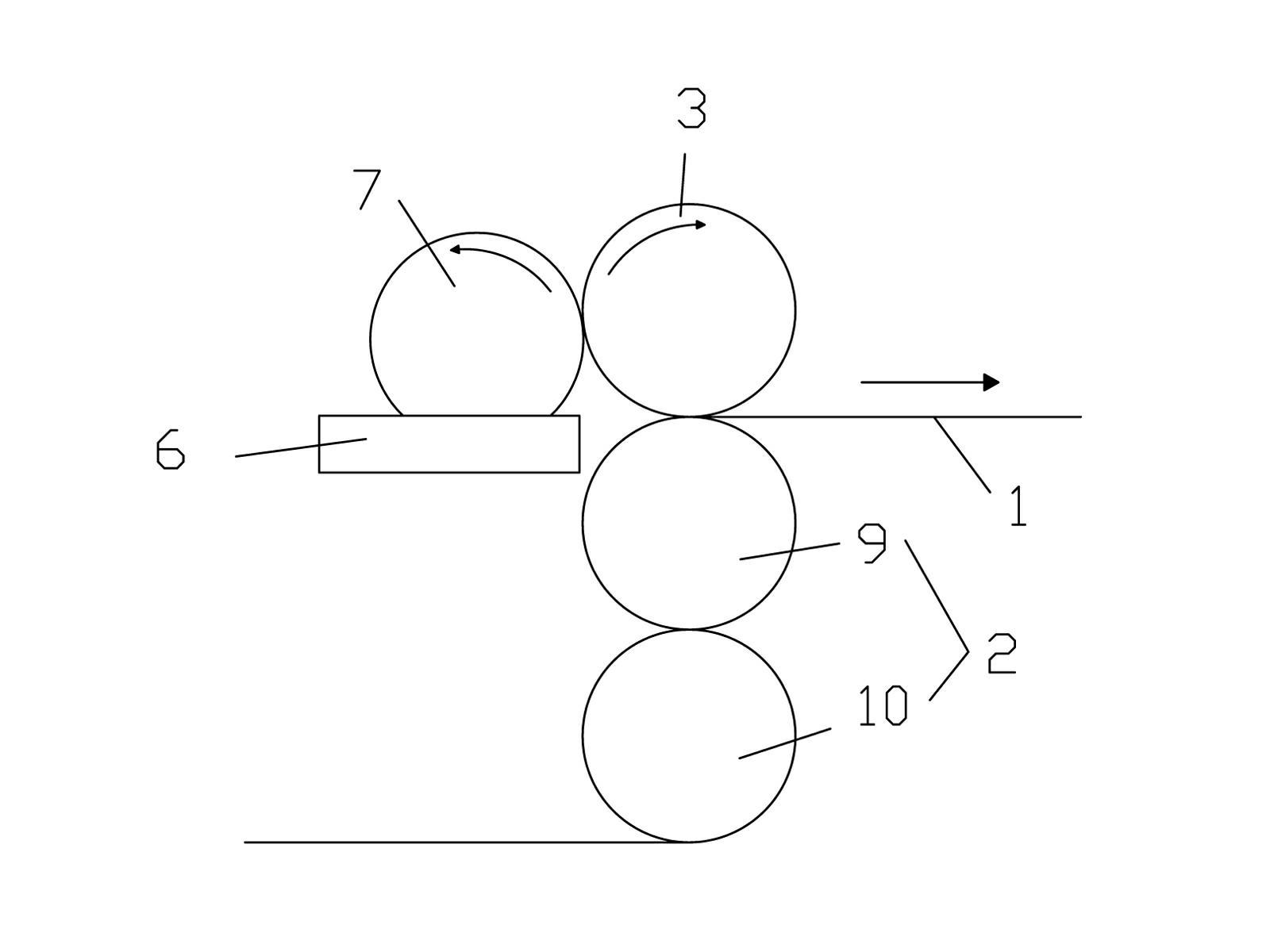
[0020] refer to figure 2 The printing material filling part 4 of this embodiment includes a printing material tank 6 and a bonding roller 7 , the bonding material roller 7 rotates in the groove of the printing material tank 6 , and the surface of the bonding material roller 7 is in close contact with the printing roller 3 . Compared with the first embodiment, this way of filling the printing material can achieve a relatively uniform filling effect, and the control of the rotation of the adhesive roller 7 is more convenient than the control of the scraper. The support member 2 of this embodiment includes an upper supporting roller 9 and a lower supporting roller 10 arranged vertically up and down and close to each other, and the coil substrate 1 is wound on the upper supporting roller 9 and the lower supporting roller in an "S" shape. 10, the arrangement of the upper support roller 9 and the lower support roller 10 allows the coil substrate 1 to pass between the two support ro...

Embodiment 3

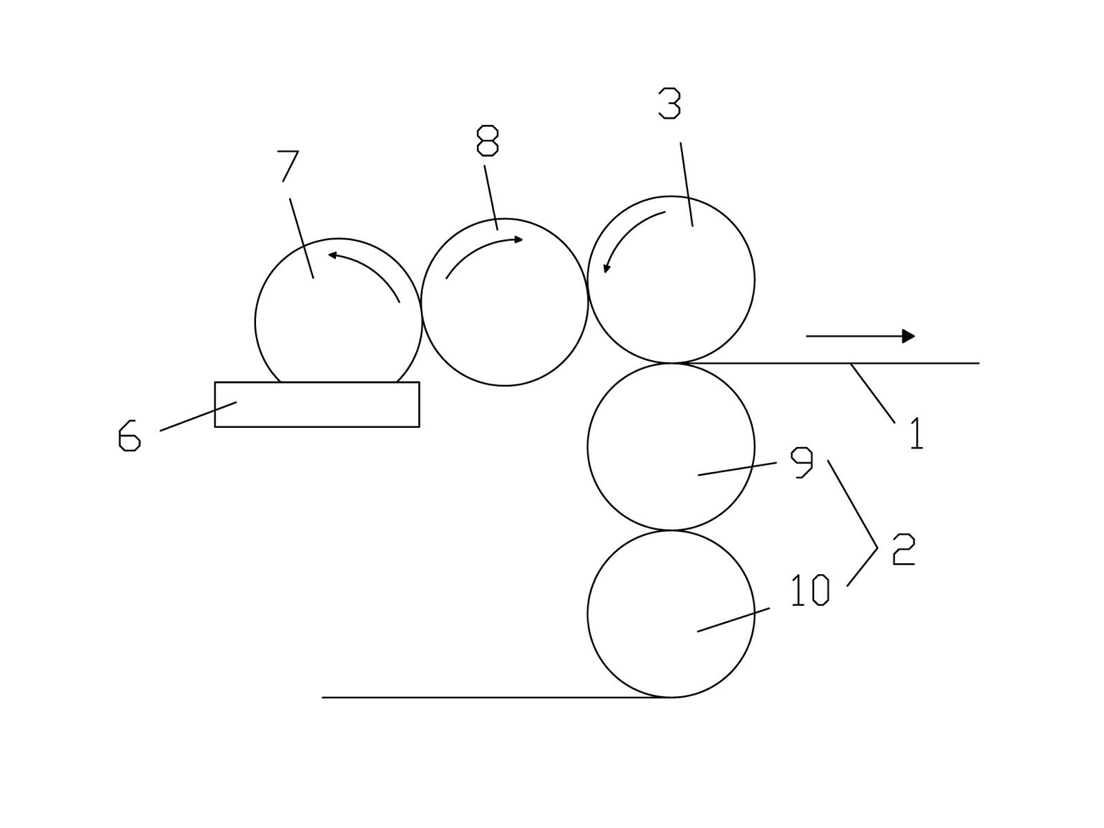
[0022] refer to image 3 The printing material filling part 4 of the present embodiment includes a printing material tank 6, a bonding material roller 7 and a transfer roller 8, the bonding material roller 7 rotates in the groove of the printing material tank 6, and the surface of the transferring material roller 8 is respectively connected to the bonding material. Material roller 7 and printing roller 3 are close to each other. Compared with the second embodiment, the structure of this printing material filling part 4 increases the middle transfer roller 8, and the setting of the transfer roller 8 can further increase the uniformity of the printing material on the printing roller, and prevent the adhesive roller 7 from printing the material tank. 6 After the adhesive is applied, it is directly coated on the printing roller 3 without treatment. Regarding the arrangement of the supporting member and the printing roller, this embodiment adopts the same setting method as that of...


PUM


Abstract

The invention discloses a rolling printing device for a metal coil and a rolling printing method for the metal coil, wherein the rolling printing device comprises a support part, a printing roller and a printing material charging part; when in rolling printing, the steps are as follows: selecting a required printing pattern, engraving the printing pattern on the surface of the printing roller, then arranging a coil baseplate on the support part, enabling the surface of the printing roller to be jointed and butted on the coil baseplate, using the printing material charging part to charge printing material onto the printing roller, moving the coil baseplate on the support part, enabling the printing roller to rotate, and using the printing roller to print the printing pattern on the coil baseplate. By adopting the rolling printing device for the metal coil, the whole rolling printing process can be continuously performed, the processing efficiency is very high, and a processed coil product has better appearance vision and anti-counterfeiting function; and the rolling printing method for the metal coil is convenient to process and simple to control, and can greatly improve the shortcomings of the traditional single-sheet plane printing and fill in a technical blank in the aspect of continuous whole coil printing.

Description

technical field [0001] The invention relates to a coating printing device and a coating printing method, in particular to a metal coil printing device and a metal coil printing method. Background technique [0002] Metal coil (such as aluminum coil, tinplate coil, copper coil, etc.) is a common material, which is widely used in packaging, protection and so on. In order to improve the visual appearance of related products, or increase the anti-counterfeiting function of the product, the surface of the metal coil is usually printed with various patterns or trademark styles. In the traditional printing of metal coils, the coiled substrates are usually cut into single pieces first, and then printed on a single sheet. The disadvantage of this printing method is that it is impossible to realize the continuous printing of the entire roll of substrates, and the production efficiency is low. In addition, the traditional printing method usually can only achieve a single solid-color c...

Claims


Application Information

Patent Timeline
Patent Type & Authority Applications(China)
IPC IPC(8): B41F17/08B41M1/28
CPCB41F9/003B41F17/08B41M1/28B41M1/10
Inventor 黎泽棉
Owner ZHUHAI SANYUAN ALUMINUM
Learn More