Seasoning apparatus
A technology of adjusting device and loading table, which is applied in the direction of stack receiving device, transportation and packaging, instruments, etc., which can solve the problems that the adjustment performance cannot be displayed, and the paper stack cannot be airtightly surrounded.
- Summary
- Abstract
- Description
- Claims
- Application Information
AI Technical Summary
Problems solved by technology
Method used
Image
Examples
no. 1 approach
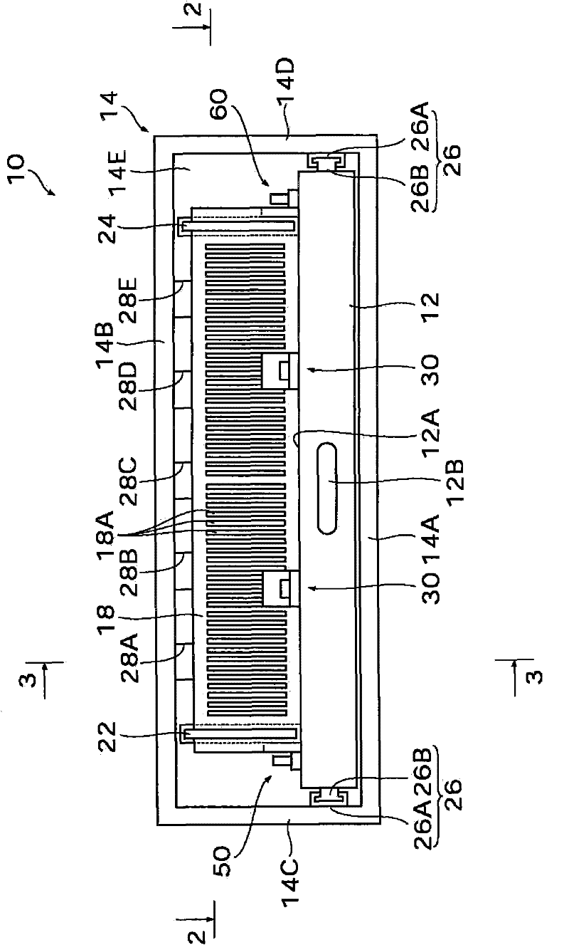
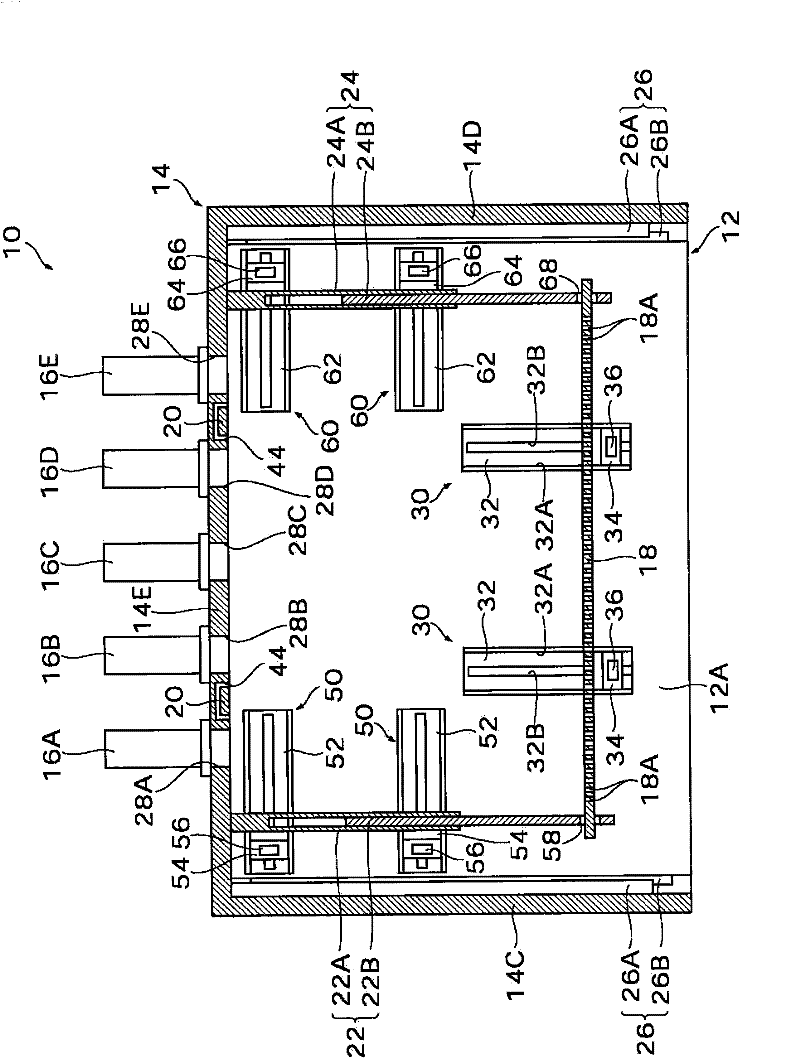
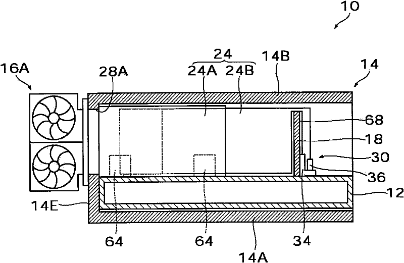
[0051] figure 1 is a front view of an adjustment device according to a first embodiment of the present invention, figure 2 and 3 are respectively along figure 1 Sectional view made by lines 2-2 and 3-3.
[0052] As shown in these figures, the adjustment device 10 includes: a mounting table 12 on which a paper stack S (shown in Figure 5A and 5B ) is loaded; housing 14, which accommodates loading table 12, a plurality of blowers 16A, 16B, 16C, 16D and 16E, which blow ambient air toward paper stack S; and side panels, which include front side panel 18, rear side A panel 14E, a left side panel 22 and a right side panel 24, which surround the stack S of paper.
[0053] The mounting table 12 is formed in a rectangular plate shape, and its upper surface serves as a horizontal loading surface 12A. A paper stack S or a stack of paper sheets is loaded onto the loading surface 12A of the stage 12 . Gripping portions 12B are formed on the front surface of the mounting table 12 . ...
no. 2 approach
[0105] Figure 6 is a front view of an adjustment device according to a second embodiment of the invention, Figure 7 is along Figure 6 The cross-sectional view at line 7-7.
[0106] In the adjusting device 10 according to the above-described first embodiment, the left side plate 22 and the right side plate 24 can be extended or retreated, and the front ends thereof are engaged with the front side plate 18 in such a manner that the left side plate 22 and the The right side panel 24 is extended or retracted accompanying the forward and rearward movement of the front side panel 18 . On the other hand, in the adjustment device 100 according to the second embodiment, each of the left side plate 22 and the right side plate 24 is constituted by a single plate, and does not protrude or recede. In addition, the engagement of the left side plate 22 and the right side plate 24 with the front side plate 18 is released in such a manner that the left side plate 22 and the right side pl...
no. 3 approach
[0110] Figure 8 is a cut-away top view of an adjustment device according to a third embodiment of the present invention.
[0111] as shown in Figure 8 , the adjustment device 200 according to the third embodiment is a modification of the adjustment device 10 of the first embodiment described above, in which the left side plate 22 is fixed on the mounting table 12 .
[0112] The left side plate 22 is constituted by a single plate and is erected vertically along the left side portion of the mounting table 12 . The left side plate 22 is fixed on the mounting table 12 , and there is no joint between the left side plate 22 and the front side plate 18 . Therefore, the front side panel 18 is only engaged with the right side panel 24 .
[0113] In the adjusting device 200 constructed as described above, it is possible to position the side plate according to the size of the paper. More specifically, since the front side plate 18 is arranged to be able to advance and retreat relat...
PUM
 Abstract
Description
Claims
Application Information
 - R&D
- Intellectual Property
- Life Sciences
- Materials
- Tech Scout
- Unparalleled Data Quality
- Higher Quality Content
- 60% Fewer Hallucinations
Browse by: Latest US Patents, China's latest patents, Technical Efficacy Thesaurus, Application Domain, Technology Topic, Popular Technical Reports.
© 2025 PatSnap. All rights reserved.Legal|Privacy policy|Modern Slavery Act Transparency Statement|Sitemap|About US| Contact US: help@patsnap.com


