
Gantry crane

A gantry crane and gantry technology, which is applied in the direction of hoisting equipment braking devices, load hanging components, bottom support structures, etc., can solve the problems of large overall wheel pressure of the crane, waste of production raw materials, and large consumption of raw materials, etc., to achieve convenience The effect of moving and installing, wheel pressure lower

Inactive Publication Date: 2011-09-21
DALIAN DAQI IND DEV
View PDF0 Cites 0 Cited by
  • Summary
  • Abstract
  • Description
  • Claims
  • Application Information

AI Technical Summary

Problems solved by technology

The door leg brackets of the gantry cranes currently used mostly adopt a solid trapezoidal structure, and a large amount of raw materials are required to connect the ends of the door frame and the door leg brackets during production, which makes the overall wheel pressure of the crane large and inconvenient to move. Installation and transportation, at the same time, cause waste of production materials

Method used


Image

  • Gantry crane
  • Gantry crane
  • Gantry crane

Examples


Embodiment Construction

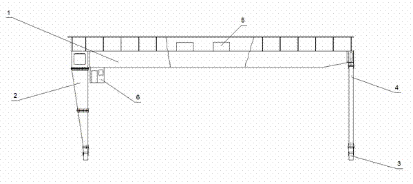
[0010] figure 1 Shown is a schematic diagram of the structure of a gantry crane. A gantry crane includes a mast 1 , a left door leg support 2 , a cart 3 , a right door leg support 4 , a trolley 5 and a driver's cab 6 . The side profile of the left door leg support 2 is an inverted trapezoid.

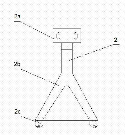
[0011] figure 2 Shown is a schematic diagram of the structure of the left door leg bracket in the gantry crane. The left door leg bracket 2 is a human-shaped structure, and is composed of a rigid leg upper crossbeam 2a, a rigid leg 2b and a rigid leg lower crossbeam 2c.

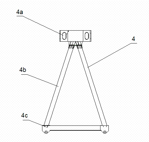
[0012] image 3 Shown is a schematic diagram of the structure of the right door leg bracket in the gantry crane. The right door leg support 4 adopts a triangular structure, and is composed of an upper crossbeam 4a, a leg 4b and a lower crossbeam 4c. In order to further reduce the wheel pressure, the right door leg support 4 adopts a hollow structure.

[0013] The door leg support structure described in the prese...


PUM


Abstract

The invention relates to the field of machinery manufacturing, in particular to a gantry crane. The gantry crane comprises a gantry, a left gantry leg bracket, a cart, a right gantry leg bracket, a dolly and a cab, wherein the left gantry leg bracket is in a Y-shaped structure and is composed of an upper rigid leg beam, a rigid leg and a lower rigid leg beam; and the right gantry leg bracket is in a triangular structure and is composed of an upper flexible leg beam, a flexible leg and a lower flexible leg beam. The gantry crane has the characteristic of low wheel pressure and is convenient to move and install.

Description

technical field [0001] The invention relates to the field of machinery manufacturing, in particular to a gantry crane. Background technique [0002] The gantry crane has a wide range of uses, and can handle various pieces and bulk materials. It has the characteristics of large operating range, high site utilization rate, and wide adaptability. The door leg brackets of the gantry cranes currently used mostly adopt a solid trapezoidal structure, and a large amount of raw materials are required to connect the ends of the door frame and the door leg brackets during production, which makes the overall wheel pressure of the crane large and inconvenient to move. Installation and transportation, meanwhile, cause waste of production raw materials. In order to solve the above problems, it is necessary to develop a new door leg bracket to solve the above problems. Contents of the invention [0003] In view of the defects existing in the prior art, the object of the present inventio...

Claims


Application Information

Patent Timeline
Patent Type & Authority Applications(China)
IPC IPC(8): B66C5/02
Inventor 李学勤于淑芳
Owner DALIAN DAQI IND DEV
Learn More