
Single-girder bridge crane composite end beam

A bridge crane and single-girder technology, which is applied in the field of hoisting machinery, can solve the problems that the lifting tonnage of single-girder bridge crane cannot meet the production demand, increase the lifting tonnage, increase user investment, etc., and achieve the purpose of increasing the traveling capacity of the cart , increase the lifting tonnage, improve the effect of economy

Pending Publication Date: 2018-11-16
沃得重工(中国)有限公司
View PDF0 Cites 0 Cited by
  • Summary
  • Abstract
  • Description
  • Claims
  • Application Information

AI Technical Summary

Problems solved by technology

[0003] With the development of production, the hoisting tonnage of the original single-girder bridge cranes of some enterprises can no longer meet the production needs, and the hoisting tonnage needs to be increased
However, the design of the plant structure and the driving girder (crane girder) are designed and manufactured according to the lifting tonnage of the existing single-girder bridge crane. The strength of the beam is not enough, and the factory building must be rebuilt to increase its structural strength or the factory building must be rebuilt to install a single-girder bridge crane with a larger lifting tonnage, thereby increasing the user's investment

Method used


Image

  • Single-girder bridge crane composite end beam
  • Single-girder bridge crane composite end beam
  • Single-girder bridge crane composite end beam

Examples


Embodiment Construction

[0019] The present invention will be further described below in conjunction with drawings and embodiments.

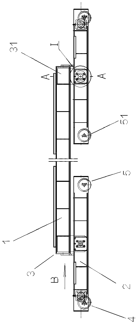
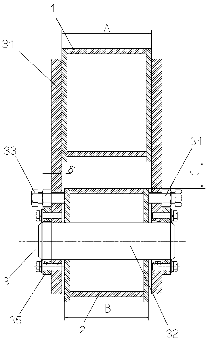
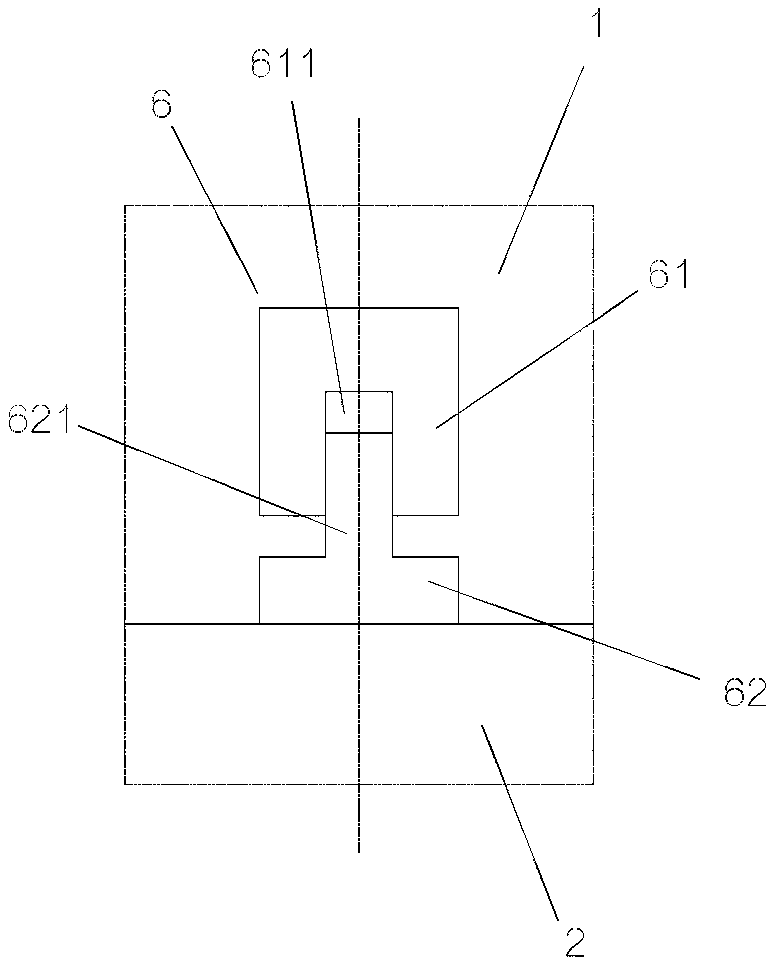
[0020] like Figure 1 to Figure 4 As shown, the present invention includes an upper end beam 1, two lower end beams 2 and hinged devices 3 respectively arranged between the two ends of the upper end beam 1 and the two lower end beams 2, one upper end beam 1 and two spaced apart The lower end beam 2 is arranged in the form of finished products up and down, and the two ends of the upper end beam 1 are respectively hinged to the middle part of the corresponding lower end beam 2 through the hinge device 3 . A drive wheel set 4 and a driven wheel set 5 are respectively arranged at both ends of each lower end beam 2 . The structure in which the four wheels 51 in the two lower end beams 2 are arranged in a straight line and supported on the crane rail on the corresponding side, and the increase in wheelbase between the frontmost wheel and the endmost wheel of the two lower en...


PUM


Abstract

The invention discloses a single-girder bridge crane composite end beam, which comprises an upper end beam, two lower end beams and hinge devices respectively arranged between two ends of the upper end beam and the two lower end beams. One upper end beam and the two lower spaced end beams are arranged in a triangular shape. The two ends of the upper end beam are respectively hinged to the middle part of the corresponding lower end beams through the hinge devices. The hinge device comprises a pair of clamping plates and mandrels. The clamping plates are respectively located on the lateral sidesof the two ends of the upper end beam. The upper end of the clamping plate is vertically fixed on the end of the upper end beam, and the middle part of the lower end beam is embedded in the lower part of the pair of clamping plates. The mandrels respectively pass through the lower ends of the pair of clamping plates and the ends of the lower end beams such that the two ends of the upper end beamare respectively hinged to the middle part of the two lower end beams. According to the invention, the lifting tonnage of a single-girder bridge crane can be increased on the basis of keeping the existing workshop structure unchanged, and the increased range can reach 80-100%. Thereby, the economy of the single-girder bridge crane is increased.

Description

technical field [0001] The invention relates to a bridge crane structure, in particular to an end beam structure at both ends of a main girder of a single girder bridge crane, and belongs to the technical field of hoisting machinery. Background technique [0002] Single-girder bridge cranes are widely used in workshops, warehouses, stockyards and other places in various fields such as mechanical metallurgy, transportation, and power stations. , the two ends of the main girder are vertically fixedly connected with the middle of the end girder respectively, and the driving wheel set and the driven wheel set are respectively set in the two ends of the end girder, and the weight of the single girder bridge crane and the weight of the lifting weight pass through the two end girders together. A total of four wheels are supported on two crane rails, and then shared to the columns through the crane girder. The single-girder bridge crane has the advantages of compact size, low build...

Claims


Application Information

Patent Timeline
IPC IPC(8): B66C6/00
CPCB66C6/00
Inventor 张弩
Owner 沃得重工(中国)有限公司
Learn More