
Full truss girder quay crane

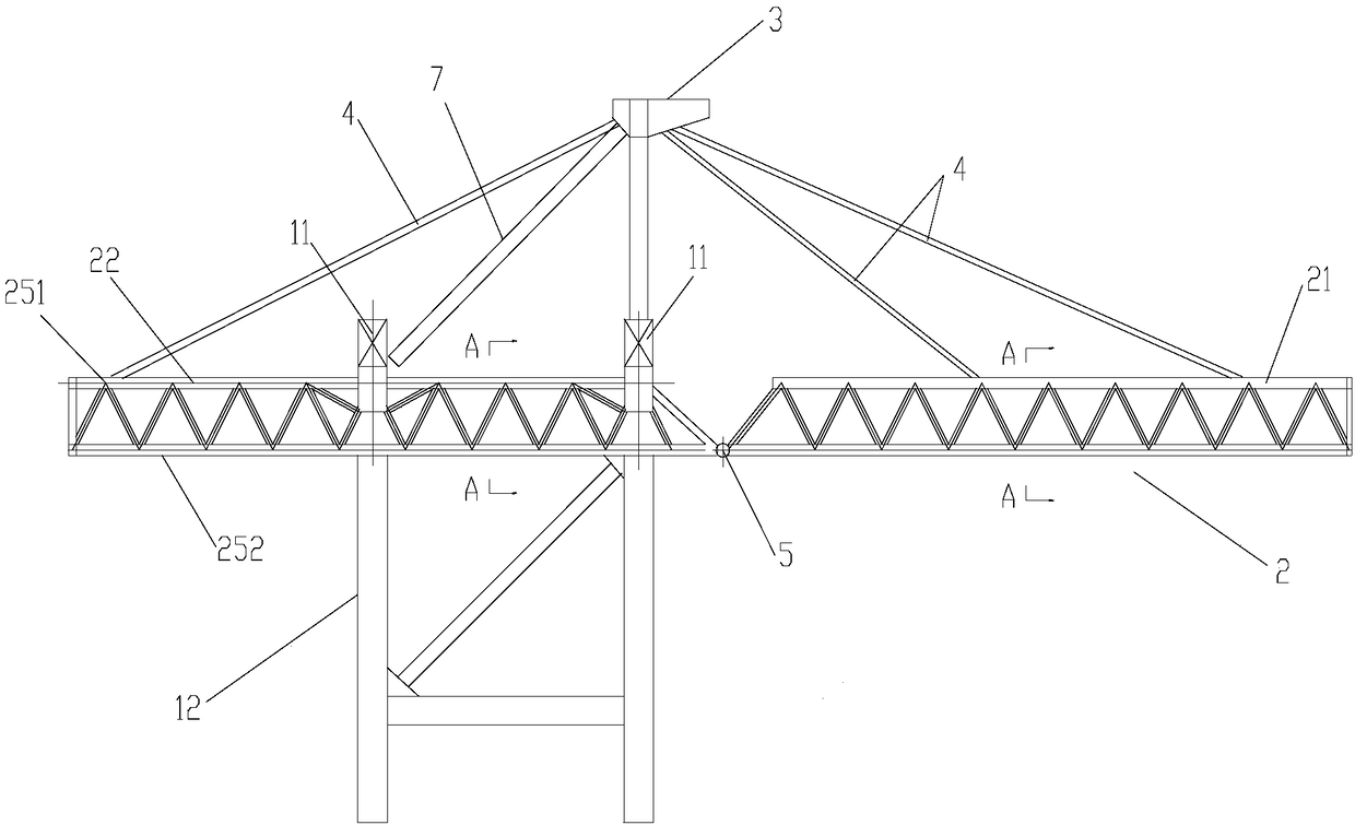
A truss-type, girder technology, applied in the field of port machinery, can solve the problems of small front extension, heavy weight of the rear girder, and large windward area, so as to reduce energy consumption, reduce its own weight and windward area, and improve practicality. sexual effect

Active Publication Date: 2018-10-12
SHANGHAI ZHENHUA HEAVY IND
View PDF11 Cites 0 Cited by
  • Summary
  • Abstract
  • Description
  • Claims
  • Application Information

AI Technical Summary

Problems solved by technology

However, because the rear extension beam is a trapezoidal plate girder truss structure, that is, the upper and lower sheet girders are set as a truss structure, while the left and right sheet girders are still solid-web plate-shaped structures, so the crane still has heavy weight, high energy consumption, and large windward area. The problem
[0006] The folding arm girder crane disclosed in the aforementioned invention patent application document CN201210431047 and the light shoreside container crane disclosed in the utility model patent document CN01253395 set the upper and lower girders of the front girder or the rear girder as a truss structure, although the weight of the quay bridge itself can be correspondingly reduced. The weight can also reduce the corresponding windward area, but because the rear girder or the left and right sheet girders of the rear girder still adopt the solid-web plate girder structure, the rear girder still has the problems of heavy weight, high energy consumption and large windward area, and It can only be applied to small quay cranes with small rated load and small forward reach

Method used


Image

  • Full truss girder quay crane
  • Full truss girder quay crane
  • Full truss girder quay crane

Examples


Embodiment Construction

[0056] The implementation of the present invention will be illustrated by specific specific examples below, and those skilled in the art can easily understand other advantages and effects of the present invention from the content disclosed in this specification. Although the description of the invention will be presented in conjunction with a preferred embodiment, it is not intended that the features of the invention be limited to that embodiment only. On the contrary, the purpose of introducing the invention in conjunction with the embodiments is to cover other options or modifications that may be extended based on the claims of the present invention. The following description contains numerous specific details in order to provide a thorough understanding of the present invention. The invention may also be practiced without these details. Also, some specific details will be omitted from the description in order to avoid obscuring or obscuring the gist of the present inventio...


PUM


Abstract

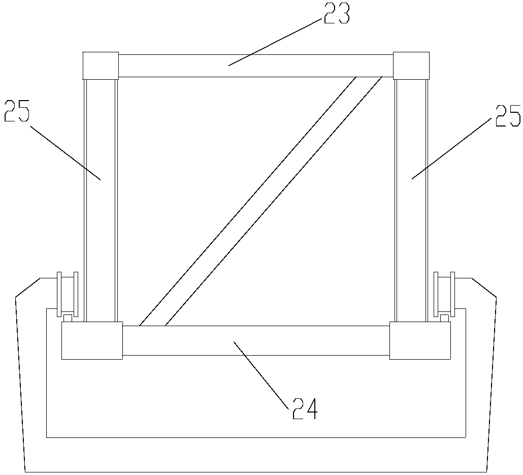
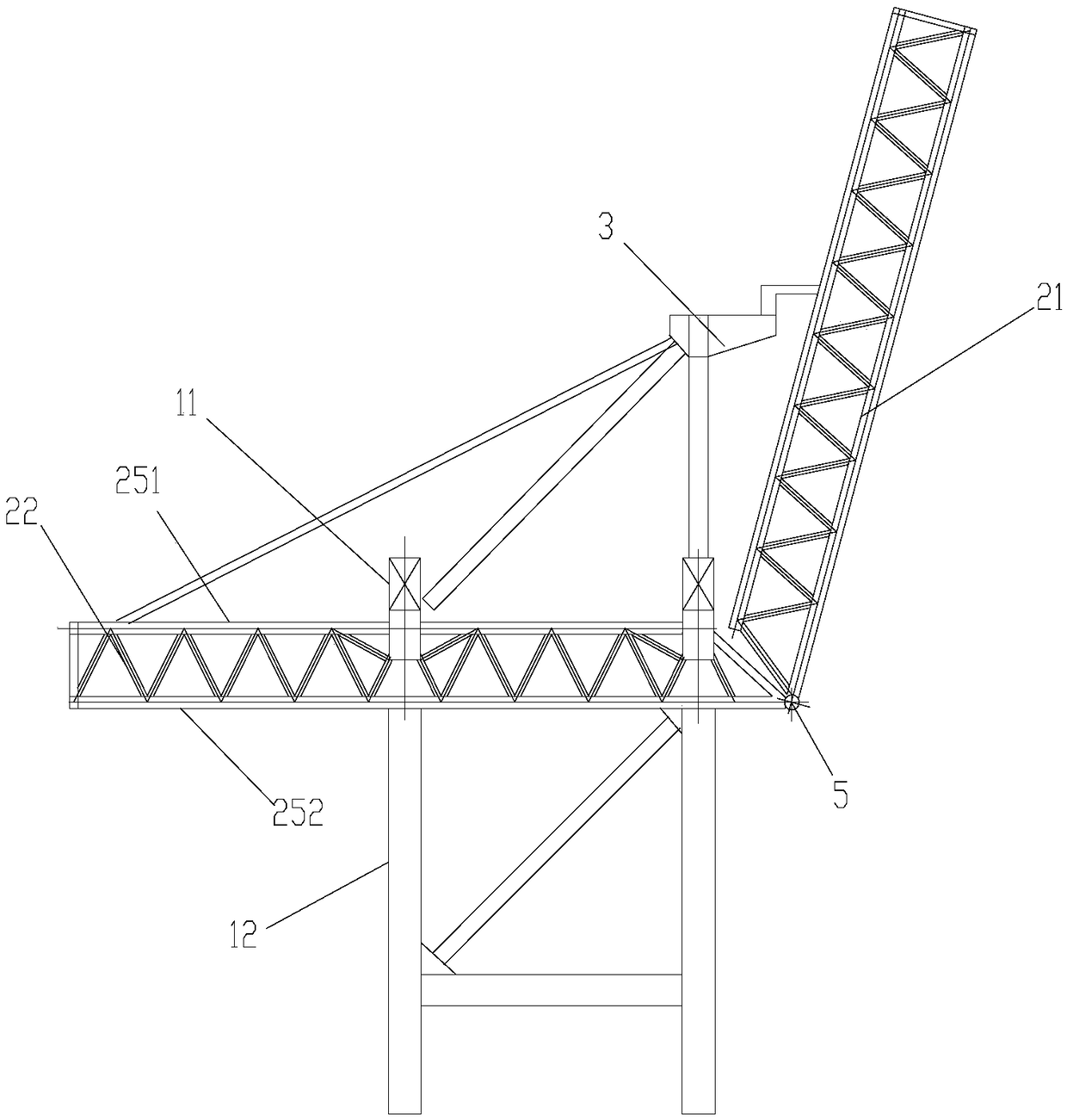
The invention relates to a full truss type quay crane with a crossbeam. The full truss type quay crane comprises a portal, the crossbeam, a trapezoidal frame and a plurality of pull rods, wherein the crossbeam and the trapezoidal frame are fixedly arranged on the portal; the plurality of pull rods are used for towing the crossbeam; the portal comprises an upper transverse beam which is horizontally arranged and portal upright columns which are arranged vertically; the crossbeam is fixedly arranged at the bottom of the upper transverse beam; the trapezoidal frame is fixedly arranged above the portal; the upper ends of the pull rods are connected with the trapezoidal frame; the lower ends of the pull rods are connected with the crossbeam; the crossbeam comprises a sea-side crossbeam and a land-side crossbeam which are connected in a rotation manner; the sea-side crossbeam and the land-side crossbeam are both quadrangular truss type crossbeams. In the full truss type quay crane with the crossbeam, which is provided by the invention, the quadrangular truss type crossbeams are adopted for both the sea-side crossbeam and the land-side crossbeam; the self weight and the windward area of the quay crane are reduced; the use energy consumption, the use cost and the generated wheel pressure of quay crane equipment are decreased; the full truss type quay crane with the crossbeam can be applicable to a big-parameter and high-grade large-sized quay crane; the practicability of large-sized quay crane equipment is improved; the full truss type quay crane with the crossbeam is worth widely popularizing and using.

Description

technical field [0001] The invention relates to the field of port machinery, in particular to a full truss type girder quay bridge. Background technique [0002] The quay crane is a kind of equipment used to load and unload the containers on the ship on the shore, and plays an irreplaceable role in the port container loading and unloading system. With the acceleration of the international trade process and the increase of port cargo volume, the quayside crane equipment is also gradually enlarged. However, due to the limitation of the carrying capacity of the wharf and the improvement of people's awareness of environmental protection, it puts forward higher requirements for the light weight and energy saving of the quay crane equipment. [0003] With the increase of the parameters of the quay bridge and the increase of the front and rear stretch, the impact of the main girder of the quay bridge on the weight, wind load and the resulting wheel pressure and energy consumption ...

Claims


Application Information

Patent Timeline
Patent Type & Authority Patents(China)
IPC IPC(8): B66C5/02B66C17/20
CPCB66C5/02B66C17/20
Inventor 林伟华李义明汪杰曾鹏张明海
Owner SHANGHAI ZHENHUA HEAVY IND
Learn More