Torque-enhanced SRM (switched reluctance motor)

A switched reluctance, motor technology, applied in the direction of magnetic circuit rotating parts, electrical components, electromechanical devices, etc., can solve the problems of large magnetic loss, difficulty in further improving motor operation control accuracy, and long magnetic circuit.

Inactive Publication Date: 2011-10-12
戴珊珊
View PDF0 Cites 14 Cited by
  • Summary
  • Abstract
  • Description
  • Claims
  • Application Information

AI Technical Summary

Problems solved by technology

However, it is precisely because the salient poles of the stator and the salient poles of the rotor are arranged radially along the rotation axis of the motor, the magnetic circuit formed by the interaction between the stator and the rotor is longer, and the magnetic loss is larger. In addition, the number of salient poles of the stator and rotor is limited by the motor Due to limitations such as volume and outer diameter, it is difficult to further improve the control accuracy of the motor operation, and at the same time it is still difficult to get rid of the torque fluctuation and noise in the operation of the switched reluctance motor

Method used


Image

  • Torque-enhanced SRM (switched reluctance motor)
  • Torque-enhanced SRM (switched reluctance motor)
  • Torque-enhanced SRM (switched reluctance motor)

Examples


Embodiment 1

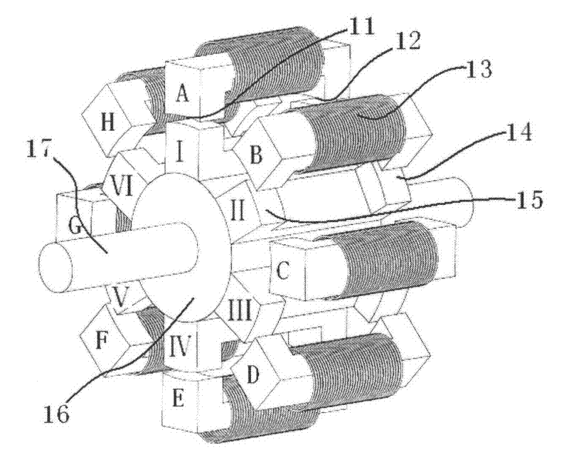
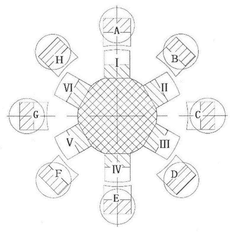
[0033] The structure of this embodiment is as attached figure 2 As shown, the structural section of this embodiment is as attached image 3 shown.

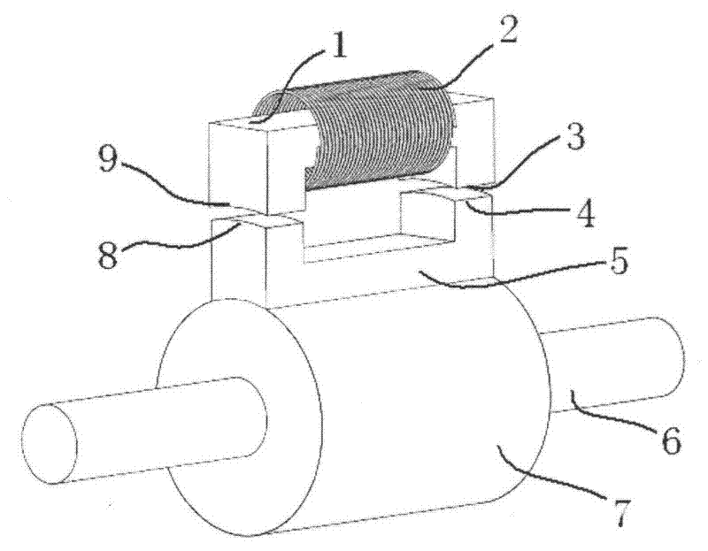
[0034] In the stator of this embodiment, there are eight doubly salient pole iron core assemblies wound with excitation coils, and these eight doubly salient pole iron core assemblies wound with excitation coils are symmetrically and evenly fixed on the inner wall of the motor housing, and the doubly salient pole iron core assemblies wound with excitation coils The magnetic salient poles 11 and 12 in the core assembly point to the motor shaft 17 . The rotor shaft seat 16 is fixed to the rotating shaft 17, and the six strip-shaped double-salient pole iron cores are symmetrically and evenly fixed on the rotor shaft seat 16 with the rotating shaft 17 as the axis of symmetry. Each strip-shaped double-salient pole iron core has two convex The protruding direction of the bar-shaped double salient core salient pole 14 and the bar-shap...

Embodiment 2

[0037] The structure of this embodiment is as attached Figure 4 shown.

[0038] This embodiment is further structured on the basis of the motor given in the first embodiment above. The motor given in the first embodiment above becomes a single motor in this embodiment. The three electric motors share one rotating shaft. as attached Figure 4 As shown, the relative positional relationship between the stators of the three motor units is exactly the same, that is, there is no rotation angle difference between the magnetic salient pole radial centerlines of the stator switch assemblies of the three motor units, and the rotors of the three motor units There is a rotation angle difference α between the radial centerlines of the salient poles of the strip-shaped double-salient pole iron core. Figure 5 A sectional view of the motor monomer at the front is given, with Figure 6 A sectional view of the motor monomer in the middle layer is given, with Figure 7 A sectional view o...

Embodiment 3

[0041] The structure of the torque-enhanced switched reluctance motor of this embodiment is the same as that of Embodiment 1 (attached figure 2 And attached image 3 As shown) the torque-enhanced switched reluctance motor is similar, the only difference is that the strip double salient pole iron core on the rotor is replaced by a double salient pole iron core assembly wound with an excitation coil.

[0042] The stator of this embodiment is composed of eight doubly salient pole iron core assemblies wound with excitation coils. The coil doubly salient pole iron core assemblies are magnetically isolated from each other, and the stator is wound with an excitation coil, and the protruding direction of the soft magnetic salient poles in the doubly salient pole iron core assembly points to the motor shaft. Each stator is wound with an excitation coil and has two magnetic salient poles. The two magnetic salient poles are axially distributed along the rotation axis. The eight assembl...


PUM


Abstract

The invention relates to a torque-enhanced SRM (switched reluctance motor) which is characterized in that the stator of the SRM is formed by even biconvex pole iron core assemblies with magnet exciting coils, wherein the even biconvex pole iron core assemblies are magnetically separated mutually and uniformly arranged on the inner wall of a motor shell annularly; two magnetic salient poles of each assembly are arranged in an axial direction; the rotor of the SRM is formed by even stripped biconvex pole iron cores which are arranged uniformly in a radial direction along an axis of rotation, and two convex poles at two ends of each stripped biconvex pole iron core are arranged in the axial direction; two magnetic convex poles of each assembly on the stator are arranged opposite to the two convex poles at two ends of each stripped biconvex pole iron core, and air gaps exist between the two magnetic convex poles of each assembly on the stator and the two convex poles at two ends of each stripped biconvex pole iron core; and the magnet exciting coils of two stator assemblies in an axial symmetry mode are connected in series or in parallel and then taken as one phase which is accessed to an excitation control power supply. In the invention, the biconvex pole iron core assemblies with the magnet exciting coils are used for replacing the stripped biconvex pole iron cores on the rotor, thus creating a motor in a similar structure. The enhanced SRM is less in magnetic loss, high in efficiency, low in impact jitter, stable in dynamic rotation and high in control accuracy.

Description

technical field [0001] The invention relates to the technical field of switched reluctance motors, in particular to a torque enhanced switched reluctance motor with a new structure. Background technique [0002] The current switched reluctance motor adopts a double-salient pole structure. The rotor is only laminated by silicon steel sheets. There is neither winding nor permanent magnet. The field winding is wound on each pole of the stator. By passing the excitation current to the stator field winding in turn, The interaction between the salient poles of the stator and the salient poles of the rotor produces torque. In the current switched reluctance motor, the magnetic circuits of the salient poles of the stator and the salient poles of the rotor are arranged radially along the rotation axis of the motor. The working principle of the switched reluctance motor follows the "principle of minimum reluctance". After power is applied, the magnetic circuit tends to change to the ...

Claims


Application Information

Patent Timeline
Patent Type & Authority Applications(China)
IPC IPC(8): H02K29/00H02K1/14H02K1/24H02K16/00
Inventor 戴珊珊陆晓峰
Owner 戴珊珊
Why Eureka
Try Eureka