Method and system of operating a fuel vapor recovering system and its engine system

A fuel vapor and recovery system technology, applied in combustion engines, internal combustion piston engines, charging systems, etc., can solve the problems of increasing component costs

Inactive Publication Date: 2011-09-21
FORD GLOBAL TECH LLC
View PDF9 Cites 27 Cited by
  • Summary
  • Abstract
  • Description
  • Claims
  • Application Information

AI Technical Summary

Problems solved by technology

As such, it increases component cost

Method used


Image

  • Method and system of operating a fuel vapor recovering system and its engine system
  • Method and system of operating a fuel vapor recovering system and its engine system
  • Method and system of operating a fuel vapor recovering system and its engine system

Examples


Embodiment Construction

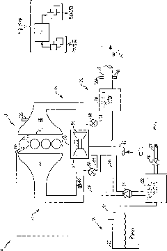
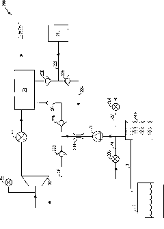
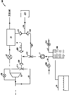
[0014] The following description relates to systems and methods for generating a vacuum generated by an ejector using a purge pump during fuel vapor canister purge and non-purge conditions. Such as Figure 1-3 As shown in , the extraction pump can be connected to the fuel vapor canister of the fuel vapor recovery system to pump the extraction flow through the fuel vapor canister to the intake manifold of the pressurized engine. One or more ejectors may be connected to the pump and may pump evacuated air through the canister, through the ejectors to the engine intake. As such, pumping the evacuation flow through the ejector may create a negative pressure at the ejector, which may be applied by the ejector to a vacuum actuator (eg, a power brake and / or a wastegate actuator). The controller can be configured to perform as Figure 4 The procedure shown in to run the extraction pump to generate vacuum at the ejector when engine boost is present. Vacuum actuation may be performed...


PUM


Abstract

A method of operating a boosted engine system is described in which a vacuum generator coupled with a fuel vapor purging system can generate vacuum during both purging and non-purging conditions, and during both boosted and non-boosted conditions. The vacuum can therefore be used to power vacuum actuated brakes, and / or other vacuum actuators, irrespective of the purging conditions, and irrespective of boost levels and irrespective of vacuum. The vehicle fuel economy and exhaust can be improved.

Description

【Technical field】 [0001] The present invention relates to a method and system for providing vacuum to multiple drives in a vehicle with a supercharged internal combustion engine, including a dynamic braking system and a fuel vapor recovery system. 【Background technique】 [0002] Vehicles may be equipped with emission control systems in which vaporized hydrocarbons (HC) released from the fuel tank (eg, during refueling) are captured and stored in an absorbent-encapsulated fuel vapor canister. Then, when the engine is running, the evaporative emissions control system may use vacuum (or pressure) to draw the vapors into the engine intake manifold for use as fuel. The evacuation flow vacuum (or pressure) may be generated by one or more pumps and / or vacuum generators. [0003] One example method of providing sufficient vacuum for the fuel evacuation flow is described in US Patent Publication US 2006 / 0196482A1. Here, the blow-by gas is delivered together with the extracted gas t...

Claims


Application Information

Patent Timeline
Patent Type & Authority Applications(China)
IPC IPC(8): F02M25/08F02D41/00F04F3/00
CPCF02M25/0836F02M25/089F02B37/127Y02T10/144F02B37/186F02B37/162Y02T10/12
Inventor R·D·普斯夫
Owner FORD GLOBAL TECH LLC
Why Eureka
Try Eureka