Improved micro switch fixing structure for electric push rod

A technology of micro switches and electric push rods, applied in the direction of electric switches, circuits, electrical components, etc., can solve the problems of small installation space, offset of travel switch position, affecting the response speed of travel switches, etc., and achieve the effect of fast and convenient installation

Inactive Publication Date: 2011-09-21
许晓华
View PDF4 Cites 0 Cited by
  • Summary
  • Abstract
  • Description
  • Claims
  • Application Information

AI Technical Summary

Problems solved by technology

[0002] In the electric push rod, the travel switch is used to control the reciprocating motion stroke of the push rod. There are direct-acting or roller-type travel switches, because the installation space is small, the structure requirements are compact, and the installation and fixing requirements of the travel switch itself are also high. It is fixed and reliable, so that the travel switch itself is fixed, and the distance between the fixed position of the travel switch and the push rod must be well controlled, so that the travel switch can respond quickly and the push rod moves in reverse, so there are certain difficulties in the fixing method. The fixing method of the travel switch in some electric push rods is shown in Figure 4. The travel switch is fixed on the long board through the wire guide at the lower end of the travel switch, and then the long board is fixed under the push rod. This structure is After the push rod works for a long time, the position of the limit switch may shift, which will affect the response speed of the limit switch. In addition, the limit switch should also be selected with a more suitable type.

Method used


Image

  • Improved micro switch fixing structure for electric push rod
  • Improved micro switch fixing structure for electric push rod
  • Improved micro switch fixing structure for electric push rod

Examples


Embodiment Construction

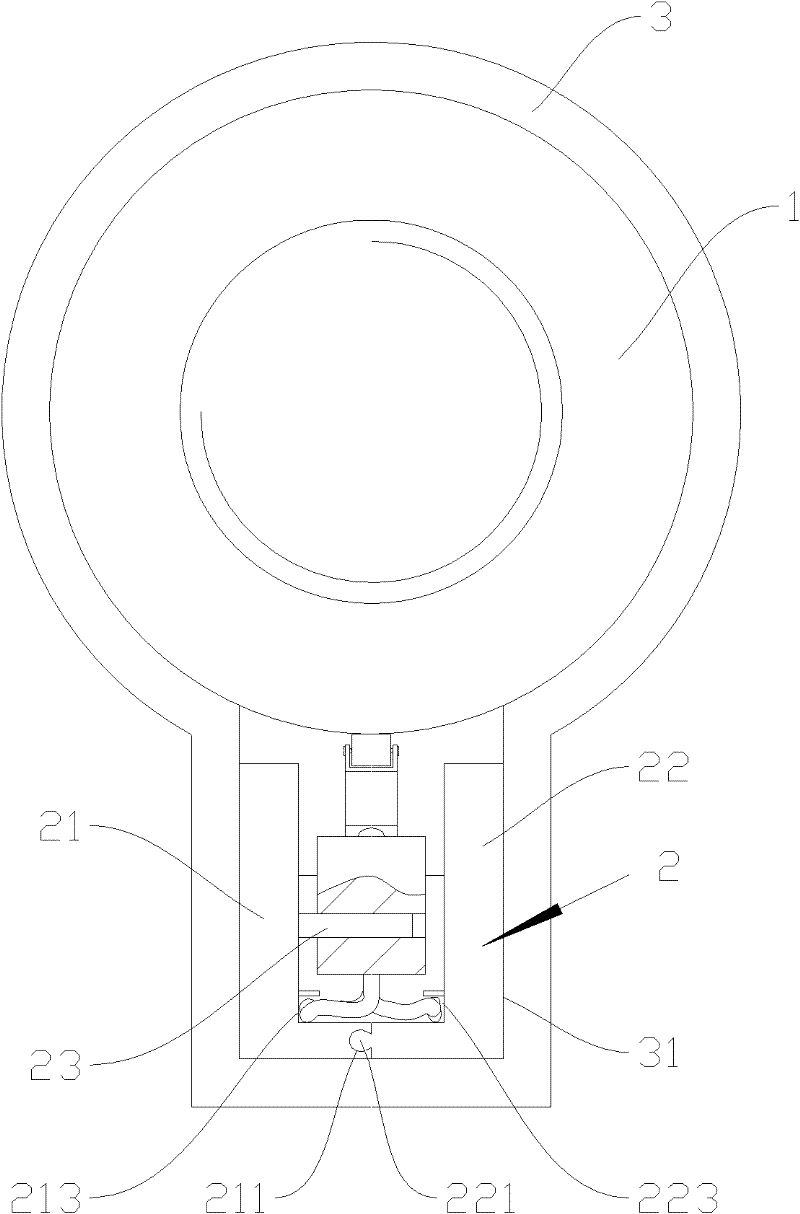
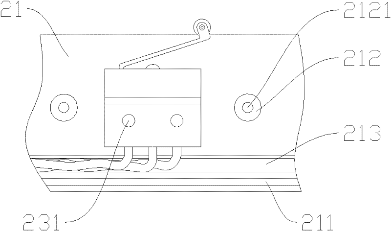
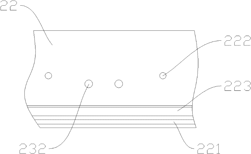
[0018] Such as Figures 1 to 3 Shown is a structural schematic diagram of an embodiment of the present invention, an improved micro switch fixing structure for an electric push rod, including a fixed plate assembly 2 arranged under the push rod 1 for fixing the micro switch, and the fixed plate assembly includes The fixed plate I21 and the fixed plate II22 that are interlocked with each other, the bottom of the fixed plate I is provided with a card slot 211, and the bottom of the fixed plate II is provided with a card bar 221 corresponding to the card slot; vertical on the inner wall of the fixed plate I There is an insertion rod 23 corresponding to the installation hole on the micro switch, and the length of the insertion rod is not greater than the width of the micro switch; between the fixed plate I and the fixed plate II, there is also a clamp to prevent the fixed plate I and the fixed plate II from The protection structure of the tight micro switch is provided with a push...


PUM


Abstract

The invention discloses an improved micro switch fixing structure. The improved micro switch fixing structure comprises a fixing plate assembly which is arranged below a push rod and used for fixing a micro switch, wherein the fixing plate assembly comprises a fixing plate I and a fixing plate II which are mutually buckled, an inserted rod corresponding to a mounting hole on the micro switch is arranged between the fixing plate I and the fixing plate II, a protective structure for preventing the fixing plate I and the fixing plate II from tightly clamping the micro switch is further arranged between the fixing plate I and the fixing plate II, a push rod sleeve is arranged outside the push rod, and the lower part of the push rod sleeve is provided with an embedding groove for the embedded mounting of the fixing plate assembly. The improved micro switch fixing structure disclosed by the invention has the advantages of simple structure and fast and convenient mounting process; after being positioned, the micro switch can be firmly fixed without any position offset; and simultaneously, the work distance between the micro switch and the push rod is ensured, so that the micro switch can rapidly respond to the action of an oscillating rod so as to enable the push rod to act in a reverse direction.

Description

technical field [0001] The invention relates to the installation and fixing of a micro switch, in particular to an improvement in the fixing structure of a micro switch for an electric push rod. Background technique [0002] In the electric push rod, the travel switch is used to control the reciprocating motion stroke of the push rod. There are direct-acting or roller-type travel switches, because the installation space is small, the structure requirements are compact, and the installation and fixing requirements of the travel switch itself are also high. It is fixed and reliable, so that the travel switch itself is fixed, and the distance between the fixed position of the travel switch and the push rod must be well controlled, so that the travel switch can respond quickly and the push rod moves in reverse, so there are certain difficulties in the fixing method. The fixing method of the travel switch in some electric push rods is shown in Figure 4. The travel switch is fixed...

Claims


Application Information

Patent Timeline
Patent Type & Authority Applications(China)
IPC IPC(8): H01H9/00H01H3/16
Inventor 马耀辉
Owner 许晓华
Why Eureka
Try Eureka