
Method for demodulating chaotic pulse position modulated communication system
A technology of pulse position modulation and demodulation method, applied in the field of communication, can solve the problems of digital information error judgment, error propagation, parameter mismatch, etc., and achieve the effect of solving high bit error rate
- Summary
- Abstract
- Description
- Claims
- Application Information
AI Technical Summary
Problems solved by technology
Method used
Image


Examples
Embodiment Construction
[0017] The present invention is a demodulation method of a chaotic pulse position modulation communication system based on particle filter. The working principle of the system is as follows:
[0018] The chaotic pulse position modulation communication system puts the binary digital information to be sent into the feedback loop, and converts the original chaotic map combined with the data information into a new map to realize modulation. The mathematical model of the system dynamic equation is:
[0019] T n+1 =F(T n )+S n+1 ×d (1)
[0020] where T n is the pulse interval, F(T n ) is the chaotic mapping function, S n It is the binary information sent by the system, which is "0" or "1", and d is the delay length caused by sending data.
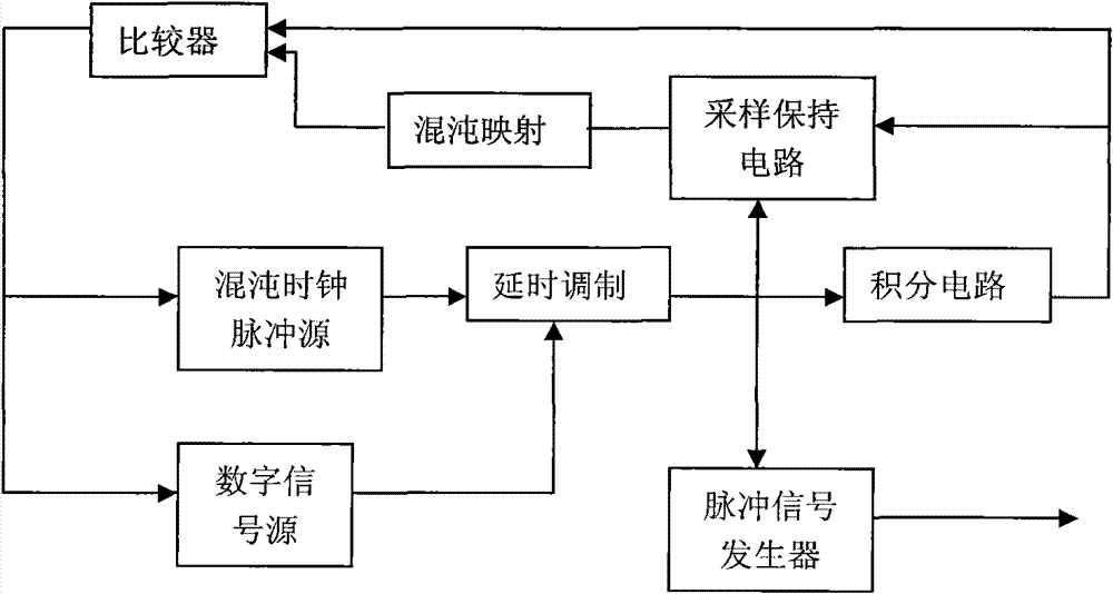
[0021] in transmitter principle figure 1 Among them, the integration circuit generates a linearly increasing voltage according to the delay of the signal, which is compared with the threshold generated by the sample-and-hold circuit and t...
PUM
 Abstract
Description
Claims
Application Information