
Time synchronization method for multi-subsystem equipment and subsystem

A time synchronization and multi-subsystem technology, applied in time division multiplexing systems, transmission systems, synchronization devices, etc., can solve the problems of no solution, no high-precision synchronization, no high-precision time synchronization chip, etc., to achieve The effect of high-precision time synchronization

Active Publication Date: 2011-09-21
NEW H3C TECH CO LTD
View PDF2 Cites 25 Cited by
  • Summary
  • Abstract
  • Description
  • Claims
  • Application Information

AI Technical Summary

Problems solved by technology

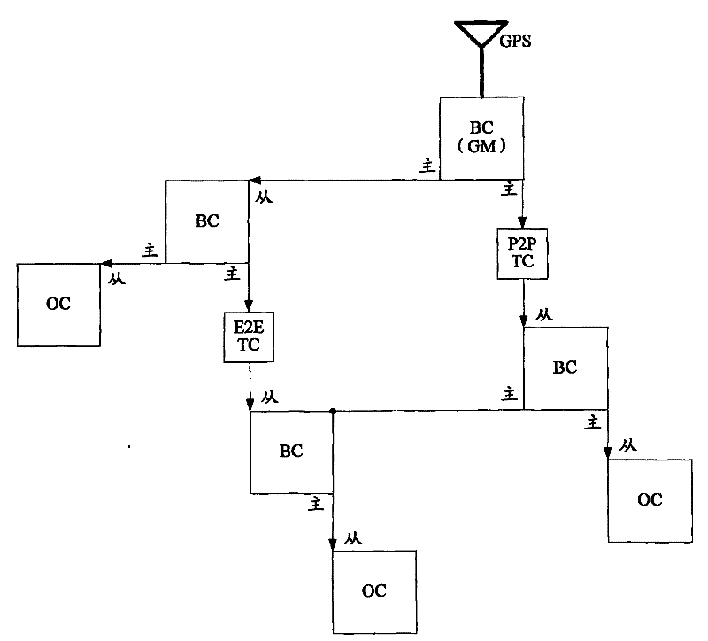
[0153] The above describes the time synchronization scheme for devices in a PTP network. However, since the PTP protocol runs on the basis of the entire device, for some devices with complex internal components, such as distributed devices, frame-type stacking devices, and frame-type cascading devices, etc. , these devices appear as a whole externally, but inside they are composed of some relatively independent subsystems. There is no high-precision time synchronization chip between the subsystems to maintain synchronization. In this way, when this type of device with multiple subsystems joins the PTP network It often happens that some subsystems of the equipment directly connected to the PTP network are synchronized with the external time source, while other subsystems that are not directly connected to the PTP network are still in local time or cannot achieve synchronization with the time source. Expected high-precision synchronization
There is currently no solution for this

Method used


Image

  • Time synchronization method for multi-subsystem equipment and subsystem
  • Time synchronization method for multi-subsystem equipment and subsystem
  • Time synchronization method for multi-subsystem equipment and subsystem

Examples


Embodiment Construction

[0194] The present invention will be further described in detail below in conjunction with the accompanying drawings and specific embodiments.

[0195] Figure 9 A flow chart of a method for time synchronization of multi-subsystem devices provided by an embodiment of the present invention, as shown in Figure 9 As shown, the specific steps are as follows:

[0196] Step 901: Configure the corresponding relationship between the clock mode of the device joining the PTP networking and the clock mode of the subsystem on the multi-subsystem device to join the PTP networking; configure PTP initialization parameters on each internal port of the multi-subsystem device.

[0197] An internal port of a multi-subsystem device refers to a port located on a certain subsystem of the multi-subsystem device and connected to another subsystem of the multi-subsystem device.

[0198] Here, when the clock mode of the device joining the PTP network is OC, the clock mode of the subsystem is BC, tha...


PUM


Abstract

The invention discloses a time synchronization method for multi-subsystem equipment and a subsystem. The method comprises that: correspondence between a clock mode of precision time protocol (PTP) networking to which the equipment is to be added and the clock modes of the subsystems is configured on the multi-subsystem equipment to be added to the PTP networking; PTP initialization parameters are configured on internal ports of the multi-subsystem equipment; each subsystem of the equipment receives the announcement that the equipment is to be added to the PTP networking, determines own clock modes according to the clock mode, carried in the announcement, of the PTP networking to which the equipment is to be added, and simultaneously performs PTP initialization according to the PTP initialization parameters configured on own internal ports, and each internal port starts running PTP functions after the initialization is finished; and each subsystem of the equipment performs PTP message interaction with other equipment in the PTP networking by the ports running the PTP functions, and performs time synchronization according to interacted PTP messages. By the method, high-precision time synchronization can be realized between all the subsystems and an external clock when the multi-subsystem equipment is added to the PTP networking.

Description

technical field [0001] The invention relates to the technical field of time synchronization, in particular to a time synchronization method and subsystems of multi-subsystem equipment. Background technique [0002] The Precision Time Protocol (PTP, Precision Time Protocol) is a high-precision time synchronization protocol proposed by the Institute of Electrical and Electronics Engineers (IEEE, Institute of Electrical and Electronics Engineers) 1588 and the IEEE802.1AS organization. In general, PTP can be roughly divided into two major functional modules, namely: [0003] 1) synchronous spanning tree module; [0004] 2) Synchronization function module. [0005] The former completes the calculation of the spanning tree, and the latter calculates the delay caused by network transmission through certain message interactions on the basis of the spanning tree, as well as the ratio of the local clock frequency to the optimal clock (GM, Grand Master) frequency, and finally calcula...

Claims


Application Information

Patent Timeline
IPC IPC(8): H04J3/06H04L29/06H04L12/56H04L7/00
CPCH04J3/0641H04J3/0697
Inventor 徐鹏飞
Owner NEW H3C TECH CO LTD
Learn More