Dust collector

A technology for vacuum cleaners and containers, which is applied in the directions of vacuum cleaners, cleaning equipment, household appliances, etc., can solve the problems of the large-scale float and the weight of the vacuum cleaner itself, and achieve the effect of eliminating unstable movements.

Inactive Publication Date: 2011-09-21
MAKITA CORP
View PDF7 Cites 0 Cited by
  • Summary
  • Abstract
  • Description
  • Claims
  • Application Information

AI Technical Summary

Problems solved by technology

Therefore, when absorbing water, etc., when the buoy 13 that rises with the rise of the water level is close to the suction port 9, the buoy 13 is sucked up before reaching the upper limit position so that the suction port 9 is blocked, and the setting of the container 2 cannot be performed. capacity to attract
However, if you use a float with a large specific attraction weight or a large size, the float will become larger or the vacuum cleaner itself will become heavier.

Method used


Image

  • Dust collector
  • Dust collector
  • Dust collector

Examples


Embodiment Construction

[0013] Embodiments of the present invention will be described below in conjunction with the accompanying drawings.

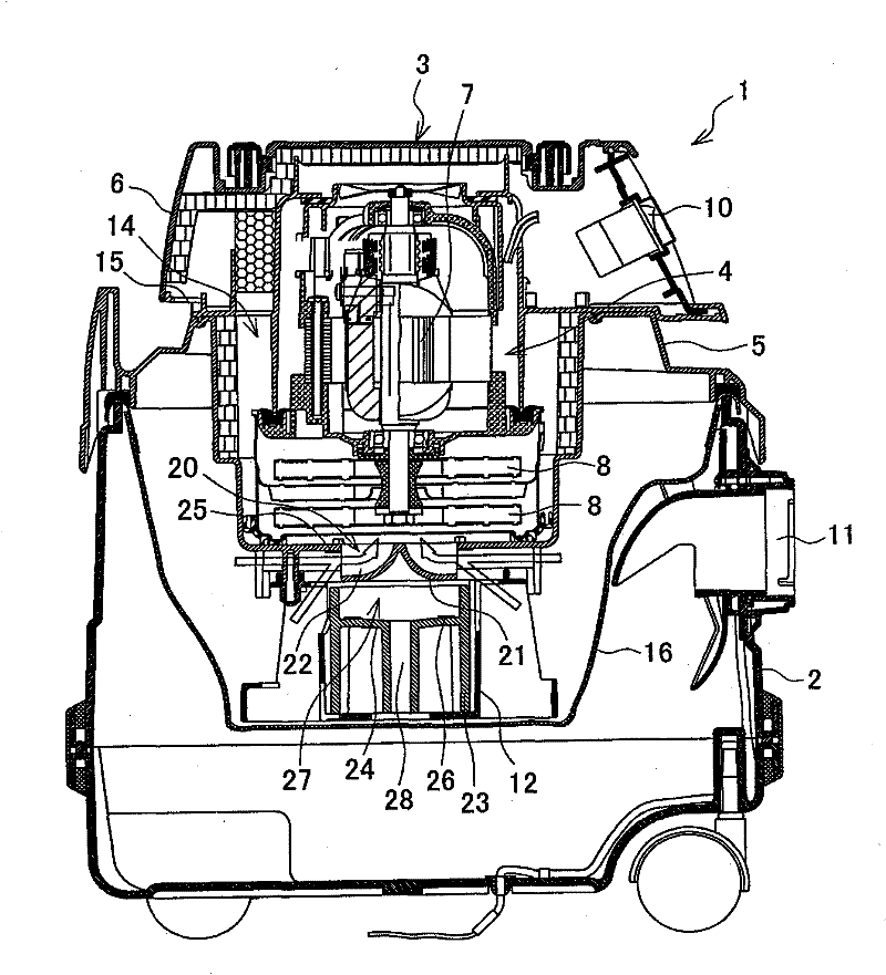
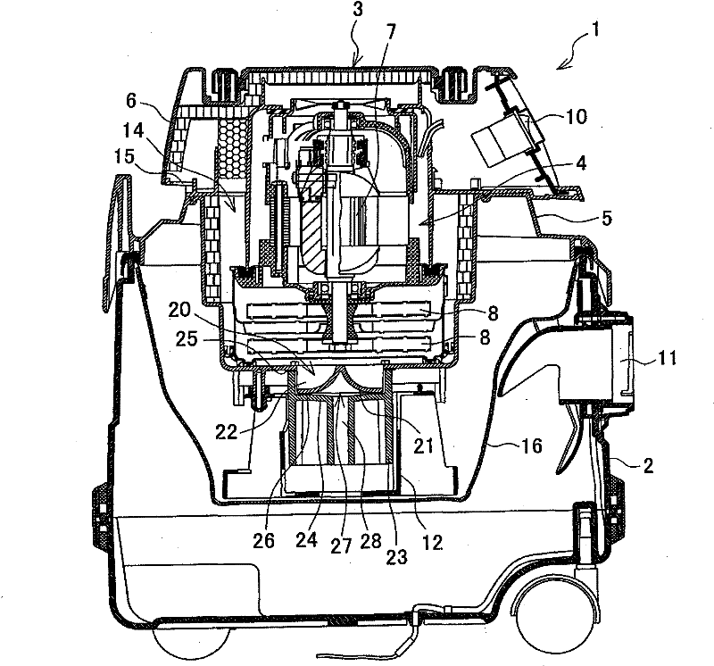
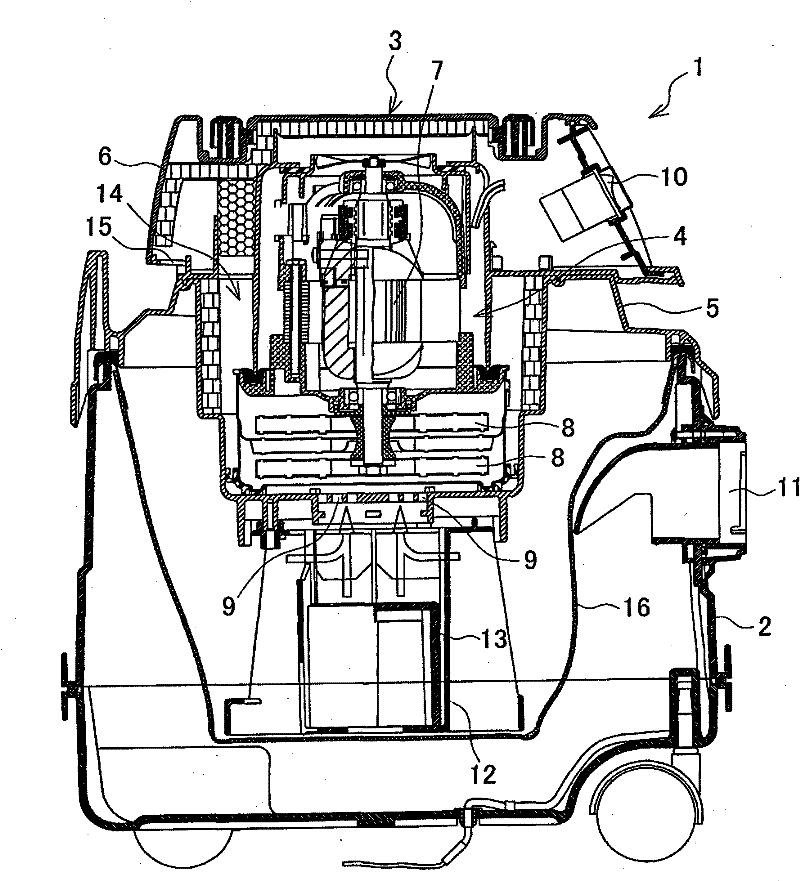
[0014] figure 1 A longitudinal sectional view showing an example of a vacuum cleaner, for which the basic structure such as a container and a body is the same as image 3 The shown conventional vacuum cleaner is the same, and the same components are given the same reference numerals, and repeated explanations are omitted, and the different components will be mainly described.

[0015] First of all, in this vacuum cleaner 1, the first difference is that the suction port 20 formed on the lower side of the suction unit 4 does not open downward, but is more open than the bottomed cylindrical container cover 5 that is the outer shell of the suction unit 4 . Also protrudes downwards and opens laterally. Specifically, the conical lower plate 21 , which is circular in plan view, is connected to the container cover 5 via the partition plate 22 , so that the horizontal ...


PUM


Abstract

Water can be reliably sucked to the set capacity of a tank by eliminating the instable operation of a float without increasing the size of the float and the weight of a dust collector. In the dust collector (1), a suction port (20) formed at the lower part of a suction unit (4) projects from the suction unit (4) downward and is opened sideways. A closing part (27) for closing the suction port (20) at the upper limit position is formed on the upper part of the float (23). Since the suction port (20) is not closed before the float (23) rises to the upper limit position, water can be surely sucked to the set capacity of the tank (2).

Description

technical field [0001] The invention relates to a vacuum cleaner which can not only suck dust but also suck liquids such as water containing dust. Background technique [0002] image 3 It is a vertical cross-sectional view of a conventional vacuum cleaner. The vacuum cleaner 1 is provided with a main body 3 having an air suction unit 4 built in above a container 2 with an open upper surface. By closing the opening of the container 2 and supporting the container cover 5 of the main body 3, the suction unit 4 is suspended and supported from the center of the container 2, and inside the suction unit 4, a motor 7 and the drive of the motor 7 are built in. The suction fan 8 that rotates down. In addition, on the container cover 5 and directly below the suction fan 8, suction ports 9 and 9 that open to the bottom of the suction unit 4 are formed. 6 is a cover covering the upper part of the main body 3, and an operation switch 10 is provided on the side. .11 is provided on the s...

Claims


Application Information

Patent Timeline
Patent Type & Authority Applications(China)
IPC IPC(8): A47L7/00
CPCA47L9/185A47L9/102A47L7/0042A47L7/0028A47L5/365
Inventor 柴田美德
Owner MAKITA CORP
Why Eureka
Try Eureka