Method for sending Minimization Driving Test measure configuration parameter, system and equipment thereof
A technology for measurement configuration and minimization, which is applied in network data management, electrical components, wireless communication, etc., and can solve problems such as UE being unable to perform MDT measurement.
- Summary
- Abstract
- Description
- Claims
- Application Information
AI Technical Summary
Problems solved by technology
Method used
Image
Examples
Embodiment 1
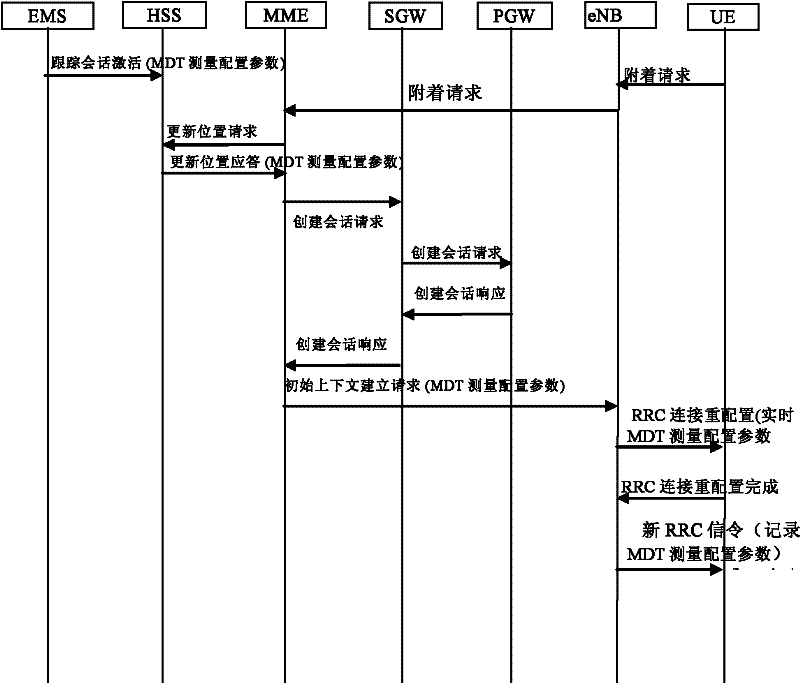
[0111] Such as Figure 7A As shown in , OAM configures an IMSI to participate in MDT measurement and the geographical area for measurement, that is, the UE corresponding to the IMSI is required A MDT measurements are performed in cell1, cell2, and cell3. UE A An RRC connection establishment request is initiated to cell4, and cell4 and cell1 belong to the same base station.
[0112] Step 1a: The EMS sends the MDT measurement configuration parameters to the HSS;
[0113] Step 1b: UE in IDLE state A Initiate an RRC connection establishment request to eNB1;
[0114] Step 2: eNB1 and UE A After establishing the RRC connection, send an initial terminal message (initial UE message) to the MME;
[0115] Step 3: The MME sends an Update Location Request (Update Location Request) message to the HSS to request the HSS to update the location of the UE in the network;
[0116] Step 4: After the HSS receives the update location request, it sends an update location answer (Update Locat...
Embodiment 2
[0122] Such as Figure 7B As shown, UE A A connection to the network has been established. The OAM configures an IMSI to participate in the MDT measurement and the geographical area where the measurement is performed, that is, the UE in the cell list is required to perform the MDT measurement in cell1, cell2, and cell3. The IMSI corresponds to the UE A .
[0123] Step 1: UE A Establish a connection with the network through eNB1, and the UE's current serving cell is cell 4;
[0124] Step 2: EMS sends a trace activation (trace activation) message to HSS, which carries MDT measurement configuration parameters;
[0125] Step 3: After receiving the tracking activation message, the HSS sends an insert subscriber data (insert subscriber data) message to the MME, carrying MDT measurement configuration parameters in the message;
[0126] Step 4: MME determines the measurement range of MDT as cell1, cell2 and cell3 according to the MDT measurement configuration parameters;
[012...
Embodiment 3
[0131] Such as Figure 7C As shown in , OAM configures an IMSI to participate in MDT measurement and the geographical area for measurement, that is, the UE corresponding to the IMSI is required A MDT measurements are performed in cell1, cell2 and cell3. UE in connected state A S1 handover is initiated, the target cell is cell 4, and cell1 and cell4 belong to the same base station.
[0132] Step 1: UE establishes a connection with the network through eNB 1;
[0133] Step 2: EMS sends trace activation message to HSS, which carries MDT measurement configuration parameters;
[0134] Step 3: After receiving the trace activation message, the HSS sends an insert subscriber data message to the MME, in which the MDT measurement configuration parameters are carried;
[0135] Step 4: MME determines the measurement range of MDT as cell1, cell2 and cell3 according to the MDT measurement configuration parameters;
[0136] Step 5: The MME judges that any cell in the MDT measurement cell...
PUM
 Abstract
Description
Claims
Application Information
 - R&D
- Intellectual Property
- Life Sciences
- Materials
- Tech Scout
- Unparalleled Data Quality
- Higher Quality Content
- 60% Fewer Hallucinations
Browse by: Latest US Patents, China's latest patents, Technical Efficacy Thesaurus, Application Domain, Technology Topic, Popular Technical Reports.
© 2025 PatSnap. All rights reserved.Legal|Privacy policy|Modern Slavery Act Transparency Statement|Sitemap|About US| Contact US: help@patsnap.com


