Self-sinking suction anchor

A suction anchor and anchor body technology, applied in fish farming, application, climate change adaptation, etc., can solve the problem of inability to multiply in the middle layer, and achieve the effect of good anchoring effect and variable resistance.

Inactive Publication Date: 2011-10-05
ZHEJIANG OCEAN UNIV
View PDF6 Cites 7 Cited by
  • Summary
  • Abstract
  • Description
  • Claims
  • Application Information

AI Technical Summary

Problems solved by technology

Like ordinary fish reefs, it adopts a sinking reef body, which can only proliferate on the bottom, and cannot proliferate on the middle layer.

Method used


Image

  • Self-sinking suction anchor
  • Self-sinking suction anchor
  • Self-sinking suction anchor

Examples


Embodiment

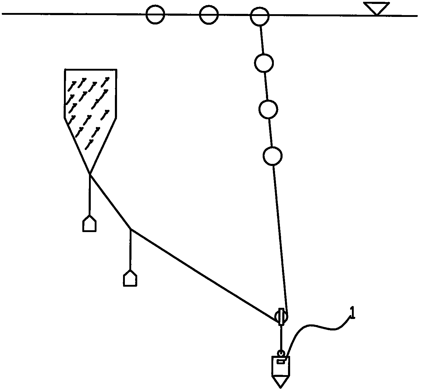
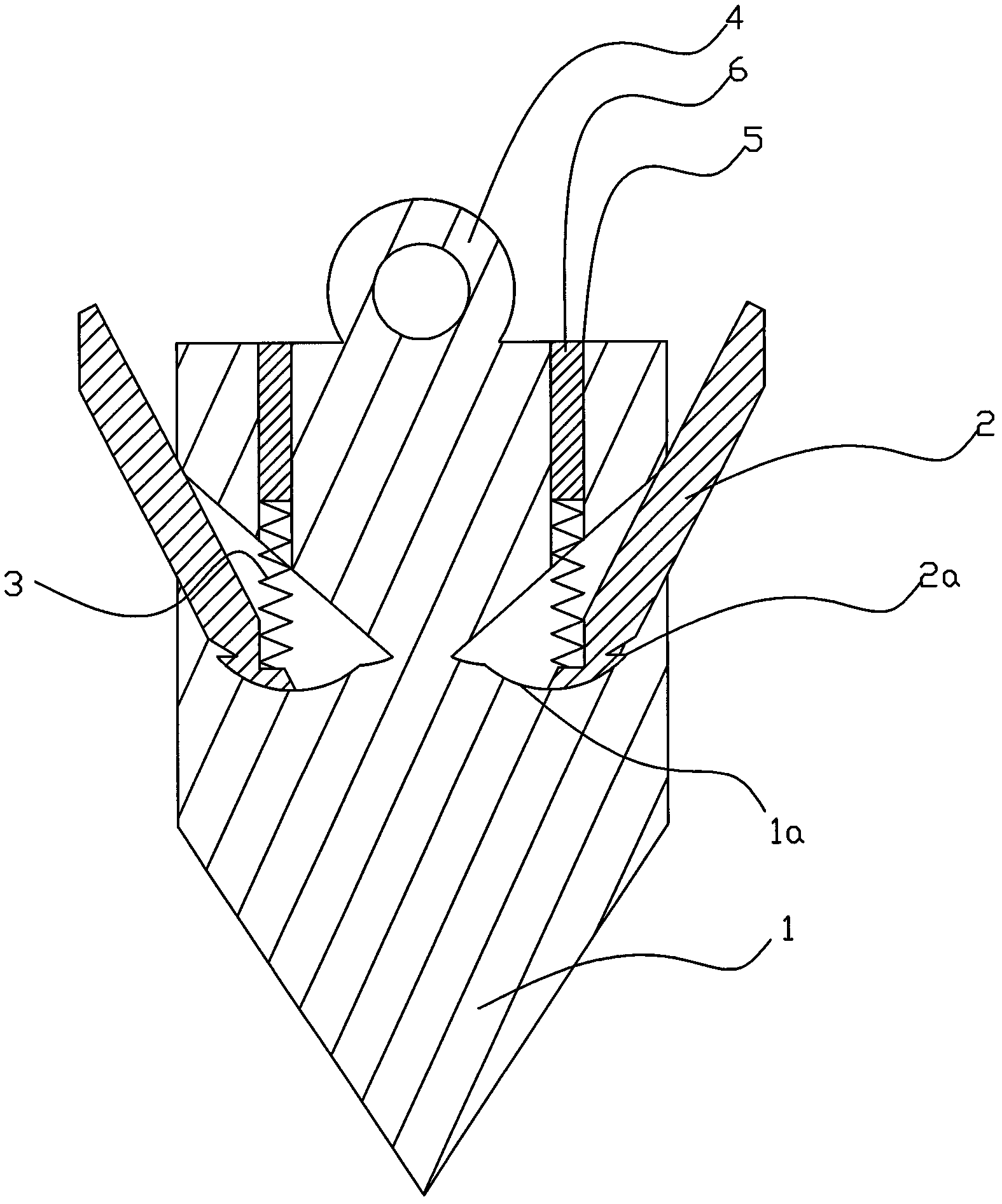
[0010] Example: refer to Figure 1 to Figure 2 The self-sinking suction anchor includes an anchor body 1, which is provided with radially arranged telescopic hooks 2; the anchor body 1 is formed with a symmetrically arranged concave activity chamber 1a that can accommodate part of the telescopic hooks 2; the activity chamber 1a A protruding structure is formed near the bottom, and a stop hook 2a is formed near the end of the telescopic hook 2 located in the movable chamber 1a; a through hole 5 is formed on the top of the anchor body 1, and the through hole 5 runs through to the movable chamber 1a; the through hole 5 is close to The part of the movable chamber 1a is provided with a spring 3; one end of the spring 3 is connected to the end of the telescopic hook 2 located in the movable chamber 1a, and the other end of the spring 3 extends into the through hole 5 and is sealed by the sealing screw 6 located in the through hole 5. Solid; the top of the anchor body 1 is shaped on ...


PUM


Abstract

The invention discloses a self-sinking suction anchor, which comprises an anchor body, wherein radially arranged telescopic hooks are arranged on the anchor; a symmetrically arranged inward concave movable cavity which can accommodate part of telescopic hooks is formed on the anchor body; a convex structure is formed near the bottom of the movable cavity, and stopping hooks are formed near the end parts of the telescopic hooks in the movable cavity; the top end of the anchor body has a through hole which runs through to the movable cavity; a spring is arranged on the part, which is close to the movable cavity, of the through hole; one end of the spring is connected with the end part of the telescopic hooks in the movable cavity, and the other end of the spring extends into the through hole and is sealed and fixed by a sealing and fixing screw in the through; and the top end of the anchor body is provided with a connecting ring. When the anchor body sinks, the telescopic hooks enter a seabed by a small acute angle to facilitate sinking. When under a pull force in an opposite direction, the telescopic hooks open transversely and are finally pressed to contract to deep positions in the movable cavity, so that a large stress area which is benefit for fixation is formed. The anchor has the advantages of variable resistance and desirable fixing effect.

Description

technical field [0001] The invention relates to a fish reef, in particular to a self-sinking suction anchor. Background technique [0002] As a fishery habitat improvement technology, artificial reef construction has played an important role in restoring fishery habitats and increasing fishery resources. The current research focus of fish reef technology is on the scientific research on the mechanism of artificial reef environment, while artificial reef As an important part of artificial reef construction, there is no in-depth research on the delivery technology and method. The deployment of artificial reefs plays a pivotal role in all aspects of artificial reef construction. Safe, accurate and efficient deployment of artificial reefs will not only enable artificial reefs to exert their maximum habitat transformation function, but also It saves a lot of manpower and material resources for the construction of artificial fish reefs. Existing artificial reefs, such as the Chi...

Claims


Application Information

Patent Timeline
Patent Type & Authority Applications(China)
IPC IPC(8): A01K61/00
CPCY02A40/81
Inventor 吴常文桂福坤徐佳晶
Owner ZHEJIANG OCEAN UNIV
Why Eureka
Try Eureka