Magnetic transmission electric gate valve

A technology of magnetic transmission and electric gate valve, applied in the direction of sliding valve, valve detail, valve device, etc., can solve the problems of leakage, difficulty, etc., and achieve the effect of reliable sealing, reduced manufacturing cost, and compact structure

Active Publication Date: 2012-07-25
SHANGHAI VALVE FACTORY
View PDF0 Cites 0 Cited by
  • Summary
  • Abstract
  • Description
  • Claims
  • Application Information

AI Technical Summary

Problems solved by technology

However, since the valve cavity is filled with fluid with certain pressure and temperature, it is easy to leak out along the gap where the valve stem protrudes.
Although people use different sealing forms such as packing to prevent this kind of leakage, it is very difficult to be sure.

Method used


Image

  • Magnetic transmission electric gate valve
  • Magnetic transmission electric gate valve

Examples


Embodiment Construction

[0015] In order to better understand the technical solution of the present invention, the following will be described in detail through specific embodiments in conjunction with the accompanying drawings:

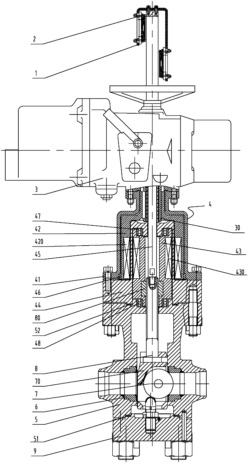
[0016] see figure 1 , a magnetic transmission electric gate valve of the present invention, comprising a bracket 1, a protective cover 2, an electric actuator 3, a magnetic transmission mechanism 4, a valve body 5, a valve seat 6, a spherical disc 7, a valve stem 8 and a bottom cover 9 . Among them, the magnetic transmission mechanism 4 is installed between the valve body 5 and the electric actuator 3; the lower part of the valve body 5 is provided with a flow channel; the valve seat 3 is respectively arranged on the inlet and outlet of the valve body flow channel; Between the flow channel inlet and outlet of the valve body; the spherical disc 7 is connected to the lower end of the valve stem 8 through the disc holder 70; the upper outer wall of the valve stem 8 is provided...


PUM


Abstract

The invention discloses a magnetic transmission electric gate valve which enables the valve to be enclosed completely. The electric gate valve comprises an electric actuating mechanism, a valve body, a valve seat, a valve rod and a magnetic transmission mechanism; the magnetic transmission mechanism comprises a support, an outer rotor, an inner rotor and a shielding cover, wherein the support is connected to the lower end of the electric actuating mechanism; the a magnetic ring is fixedly embedded on an inner cavity wall at the lower part of the outer rotor; the outer rotor can rotatably installed in the inner cavity of the support, and the upper end of the outer rotor is connected with the electric actuating mechanism; a valve rod nut is fixedly embedded on the inner cavity wall at the lower part of the inner rotor; a magnetic ring is fixedly sleeved on the outer wall at the middle part of the inner rotor; the inner rotor is installed in the inner cavity of the outer rotor, thus the valve rod nut is spirally sleeved on the upper part of the valve rod; and the shielding cover is installed between the outer rotor and the inner rotor, and a flange at the lower part of the shielding cover is connected between the upper end surface of the valve body and the lower end surface of the support.

Description

technical field [0001] The invention relates to a gate valve, in particular to a magnetic drive electric gate valve. Background technique [0002] In general, the electric gate valve is driven by the electric actuator to move the valve stem, and rotates clockwise or counterclockwise to close or open the valve. Since the electric actuator cannot be installed in the valve body cavity, it can only be installed outside the valve body cavity, and the electric actuator is connected to the valve through the valve stem, and the torque required for opening and closing the valve provided by the electric actuator is transmitted through the valve stem. . However, since the valve cavity is filled with fluid with a certain pressure and temperature, it is easy to leak out along the gap of the valve stem protruding part. Although people adopt different sealing forms such as packing to prevent this leakage, it is very difficult to be sure. Contents of the invention [0003] The object o...

Claims


Application Information

Patent Timeline
Patent Type & Authority Patents(China)
IPC IPC(8): F16K31/04F16K31/06F16K3/00F16K37/00F16K41/00
Inventor 刘其斌王建克刘少良吴宇萍顾朝党
Owner SHANGHAI VALVE FACTORY
Why Eureka
Try Eureka