Method, device and system for generating monitoring interfaces of equipment

A technology for equipment monitoring and interface generation, which is applied in the direction of program control devices, lighting devices, lamp circuit layout, etc., can solve the problems of poor diversity and flexibility, and low efficiency of customized equipment monitoring interfaces, and achieve the effect of solving excessive workload

Inactive Publication Date: 2011-10-05
OCEANS KING LIGHTING SCI&TECH CO LTD +1
View PDF3 Cites 41 Cited by
  • Summary
  • Abstract
  • Description
  • Claims
  • Application Information

AI Technical Summary

Problems solved by technology

[0005] The purpose of the embodiments of the present invention is to provide a method for generating a device monitoring interface

Method used


Image

  • Method, device and system for generating monitoring interfaces of equipment
  • Method, device and system for generating monitoring interfaces of equipment
  • Method, device and system for generating monitoring interfaces of equipment

Examples


Embodiment Construction

[0023] In order to make the object, technical solution and advantages of the present invention clearer, the present invention will be further described in detail below in conjunction with the accompanying drawings and embodiments. It should be understood that the specific embodiments described here are only used to explain the present invention, not to limit the present invention.

[0024] The embodiment of the present invention utilizes the graphical control method to generate the graphical control, and the user can generate a personalized graphical monitoring interface according to the user's needs, so as to effectively exert the effectiveness of the equipment monitoring system.

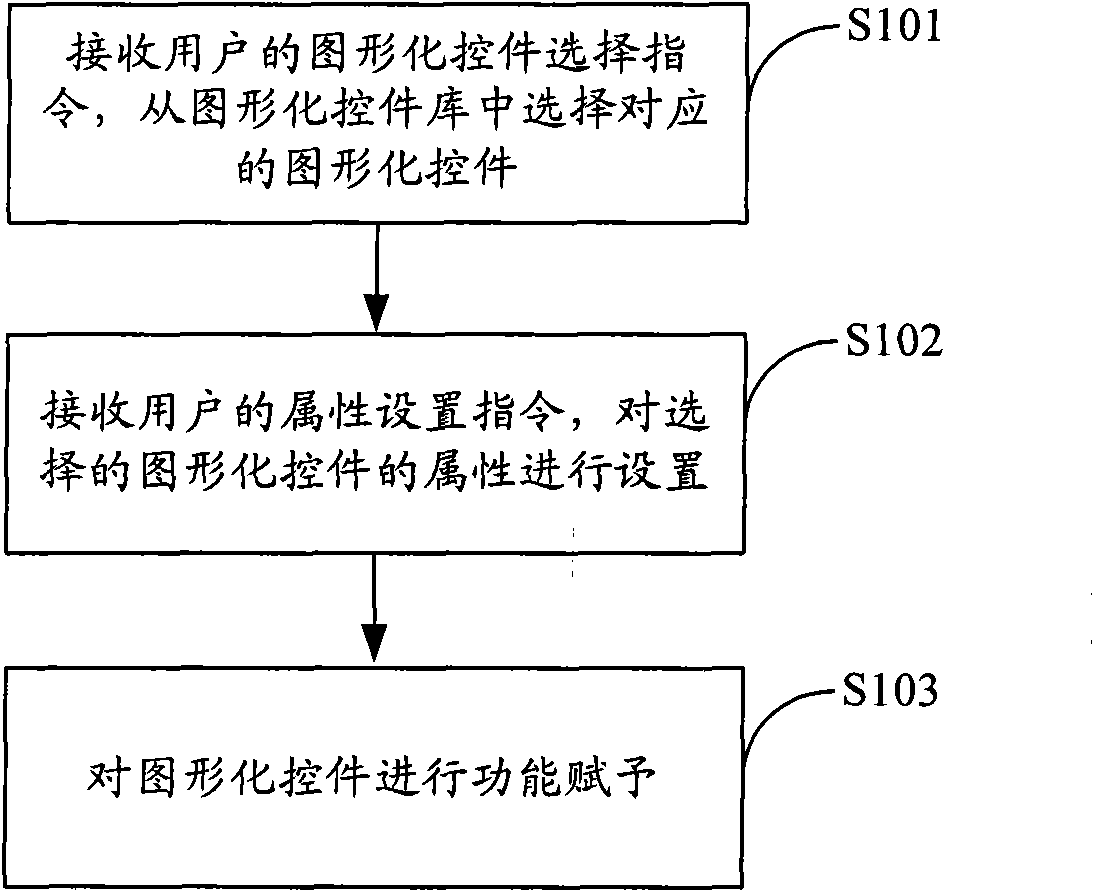
[0025] figure 1 The implementation process of the device monitoring interface generation method provided by the embodiment of the present invention is shown, and the details are as follows:

[0026] In step S101, receive a graphical control selection instruction from the user, and select a corresp...


PUM


Abstract

The invention is applied to the field of computer control and provides a method, a device and a system for generating monitoring interfaces of equipment. The method comprises the following steps of: receiving a graphic ActiveX selection instruction of a user, and selecting a corresponding graphic ActiveX from a graphic ActiveX library; receiving an attribute setting instruction of the user, and setting an attribute of the graphic ActiveX; and endowing the graphic ActiveX with functions. According to all kinds of control equipment attribute information which is configured in an equipment monitoring system, and based on an expandable graphic ActiveX library, various graphic monitoring interfaces are automatically generated, stored and realized directly, so the problem that the monitoring interfaces of fixed equipment cannot adapt to the change of monitoring requirements of the user is solved, the defects of over-high working capacity and poor normalization brought by manual customization of all monitoring interfaces are overcome, and effects of flexibility and high efficiency are achieved.

Description

technical field [0001] The invention is applicable to the field of computer control, and in particular relates to a method, device and system for generating an equipment monitoring interface. Background technique [0002] General equipment monitoring systems, such as intelligent lighting control systems, will provide users with a graphical monitoring interface for users to perform software functions, monitor the value and status of various monitored objects such as lamps and lighting control equipment, etc. Real-time information. [0003] At present, the monitoring interface of the equipment monitoring system is designed according to user needs in the design stage, that is, pre-configured, arranged, and defined for each functional element included in it. It will not change after release and is suitable for simple and fixed monitoring systems. Some equipment monitoring systems can also provide users with a simple configuration environment and a set of tools (interface compon...

Claims


Application Information

Patent Timeline
IPC IPC(8): G06F9/44H05B37/02
Inventor 周明杰李卫
Owner OCEANS KING LIGHTING SCI&TECH CO LTD
Why Eureka
Try Eureka