Method and device for a magnetic resonance system control sequence

一种控制序列、确定装置的技术,应用在测量装置、应用、测量磁变量等方向,能够解决发射功率低、不能产生图像等问题

Inactive Publication Date: 2011-10-12
SIEMENS HEALTHCARE GMBH
View PDF3 Cites 30 Cited by
  • Summary
  • Abstract
  • Description
  • Claims
  • Application Information

AI Technical Summary

Problems solved by technology

On the other hand, the resulting high-frequency limitation is unacceptable for the performance of clinical imaging, since the total transmit power may be too low to produce acceptable images considering such hot spots

Method used


Image

  • Method and device for a magnetic resonance system control sequence
  • Method and device for a magnetic resonance system control sequence
  • Method and device for a magnetic resonance system control sequence

Examples


Embodiment Construction

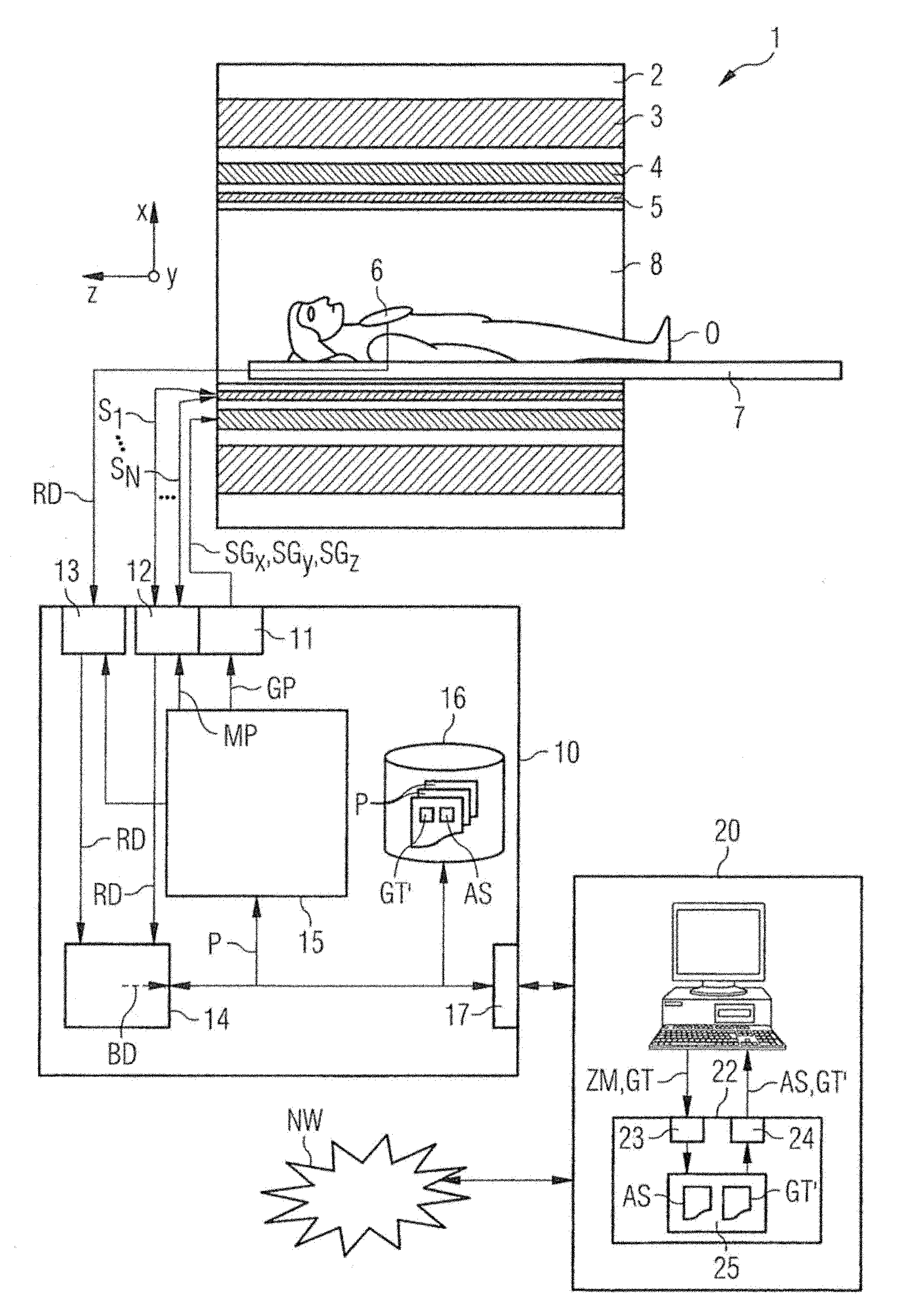
[0035] exist figure 1 The magnetic resonance system 1 according to the invention is shown roughly schematically in . The magnetic resonance system comprises, on the one hand, the actual magnetic resonance scanner 2 as well as an examination space 8 or patient tunnel located in the magnetic resonance scanner. The couch 7 can enter into the patient channel 8, so that the patient O or the examinee on the couch can be placed in the magnetic resonance scanner 2 during the examination relative to the magnetic system and the high-frequency system arranged in the magnetic resonance scanner. position, or move between different positions during the measurement.

[0036] The main components of the magnetic resonance scanner 2 are the basic field magnet 3 , the gradient system 4 with magnetic field gradient coils for imposing arbitrary magnetic field gradients in the x, y and z directions, and the integral high-frequency coil 5 . The magnetic resonance signals induced in the examination...


PUM


Abstract

A method and a control sequence determination device 22 for determining a magnetic resonance system control sequence AS is provided. A multichannel pulse train MP with a plurality of individual RF pulse trains S1..., SN is sent out by a magnetic resonance system over different independent radio-frequency channels in parallel. Based on a prespecified k-space gradient trajectory GT and a prespecified target magnetization ZM, a multichannel pulse train MP is calculated in an RF pulse optimization method, where in an RF exposure optimization method, the k-space gradient trajectory GT is optimized using a function parameterizable at least with respect to an RF exposure value of an object O under examination. The invention also describes a method for operating the magnetic resonance system (1) and a magnetic resonance system (1) having the control sequence determination device 22.

Description

technical field [0001] The present invention relates to a method and a control sequence determination device for determining a control sequence of a magnetic resonance system, the control sequence of the magnetic resonance system includes a plurality of independent signals transmitted in parallel by the magnetic resonance system through different high-frequency transmission channels independent of each other A multi-channel pulse train of a high-frequency pulse train, wherein the multi-channel pulse train is calculated with a high-frequency pulse optimization method based on a predetermined k-space gradient trajectory and a predetermined target magnetization. Furthermore, the invention relates to a method for operating a magnetic resonance system with a plurality of mutually independent high-frequency transmission channels using such a magnetic resonance system control sequence, and to a magnetic resonance system with A plurality of mutually independent high-frequency transmis...

Claims


Application Information

Patent Timeline
Patent Type & Authority Applications(China)
IPC IPC(8): A61B5/055
CPCG01R33/4824G01R33/5612
Inventor 乔格·莫斯南格迪特尔·里特
Owner SIEMENS HEALTHCARE GMBH
Why Eureka
Try Eureka