
Dynamic sar emission control for minimizing rf exposure

An action and radio frequency technology, applied in electrical components, wireless communication, transmission systems, etc., can solve the problems of UE output power reduction, UE power backoff, not very strict, etc.

Inactive Publication Date: 2016-02-24
TELEFON AB LM ERICSSON (PUBL)
View PDF9 Cites 0 Cited by
  • Summary
  • Abstract
  • Description
  • Claims
  • Application Information

AI Technical Summary

Problems solved by technology

In some scenarios, a fixed SAR value may result in excessive UE power backoff or cause less than required UE output power reduction
In addition, the SAR requirements may change in the future, i.e. they may become stricter or less stringent

Method used


Image

  • Dynamic sar emission control for minimizing rf exposure
  • Dynamic sar emission control for minimizing rf exposure
  • Dynamic sar emission control for minimizing rf exposure

Examples


Embodiment Construction

[0035] The following description sets forth specific details (eg, specific embodiments) for purposes of explanation and not limitation. It will be understood, however, by those skilled in the art that other embodiments may be employed without these specific details. In some instances, detailed descriptions of well-known methods, interfaces, circuits, and devices are omitted in order not to obscure the description with unnecessary detail. Individual boxes are shown in the diagram corresponding to various nodes. Those skilled in the art will appreciate that individual hardware circuits, software programs and data in conjunction with a suitably programmed digital microprocessor or general purpose computer, and / or application specific integrated circuits (ASICs), and / or one or more Multiple digital signal processors (DSPs) implement the functions of those blocks. Nodes that communicate using the air interface also have suitable radio communication circuitry. Software program in...


PUM


Abstract

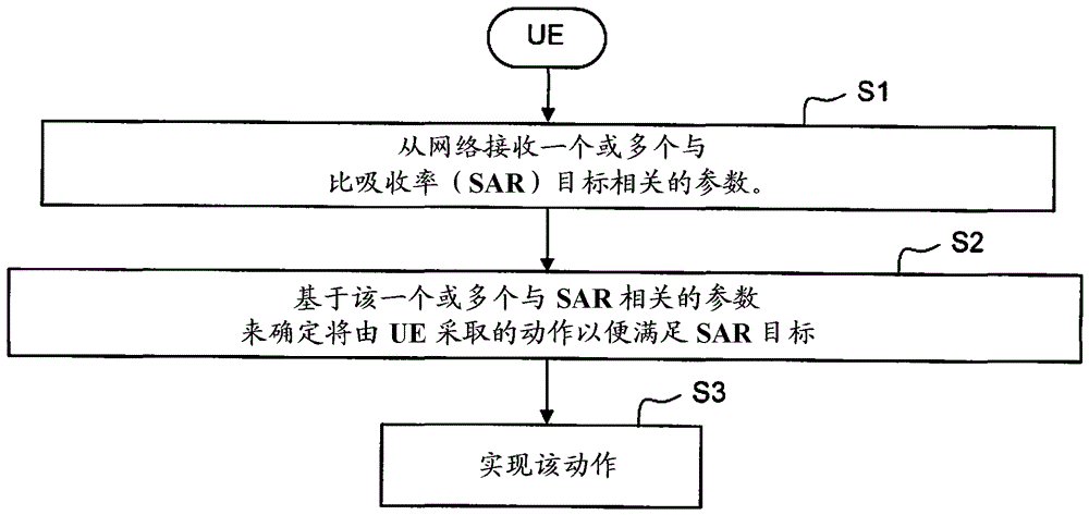
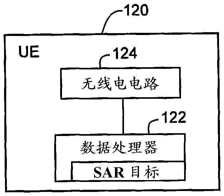
Network nodes (10, 100) determine one or more parameters related to a specific absorption rate (SAR) target, where SAR is the maximum energy or power absorbed by a unit mass of tissue exposed to radio frequency (RF) electromagnetic field (EMF) radiation. What is the measurement of the RF? EMF radiation is generated due to radio transmissions generated by the UE (12, 120). The network node generates content for the message for transmission to the UE, the content containing the determined one or more SAR related parameters to be applied by the transmitter in the UE. Based on those one or more SAR related parameters, the UE determines and implements actions in order to meet the SAR objectives. Other example embodiments allow the UE to determine SAR-related parameters in other ways.

Description

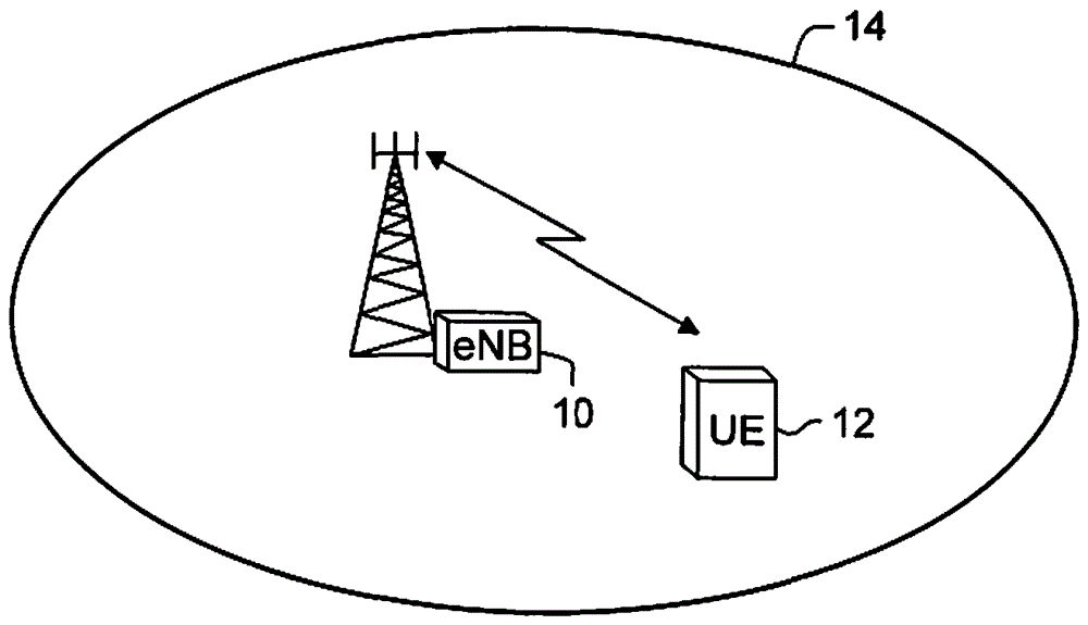
technical field [0001] This technology relates to radio communications, and in particular to radio transmission control as it relates to Specific Absorption Rate (SAR) requirements. Background technique [0002] figure 1 A cellular communication system is shown having a serving node 10 (depending on the system, it may be referred to as a base station, Node B, evolved Node B (eNodeB or eNB), etc.) serving a service geographical area located at the serving node A user equipment (UE) 12 within a cell (referred to as a cell 14). Communication is performed bidirectionally between eNB10 and UE12. Communication from eNB 10 to UE 12 is said to occur in the downlink direction, while communication from UE 12 to eNB 10 is said to occur in the uplink direction. [0003] In E-UTRAN, Orthogonal Frequency Division Multiple Access (OFDMA) technology is used in downlink and Single Carrier Frequency Division Multiple Access (SC-FDMA) is used in uplink. In both uplink and downlink, data tr...

Claims


Application Information

Patent Timeline
IPC IPC(8): H04B1/3827H04W36/00H04W52/36
CPCH04W36/0072H04W52/367H04B1/3838H04W36/304H04W36/30
Inventor M.卡兹米
Owner TELEFON AB LM ERICSSON (PUBL)
Learn More