Magnetic tracking system

a tracking system and magnetic field technology, applied in the field of magnetic tracking systems, can solve the problems of limiting the attainable field strength or the achievable level of detection signal amplitude, introducing distortions into the expected or calibrated field distribution, and varying magnetic fields induce eddy currents in conductive structures found within the field, so as to enhance the accuracy of tracking determination and enhance the accuracy of p&o determination

Inactive Publication Date: 2005-12-27
NORTHERN DIGITAL
View PDF37 Cites 219 Cited by
  • Summary
  • Abstract
  • Description
  • Claims
  • Application Information

AI Technical Summary

Benefits of technology

[0018]Since mutual inductance is a symmetric property, i.e., depending simply on the geometries of the transmission and receiving coils and their relative positions, the system may interchange transmitter and receiver units, employing quite small coil assemblies, yet use a model that gives a direct computation of coordinates without excessive iterative approximations, and without resort to the multitude of gain level and other normalization corrections otherwise typically needed when working from magnetic field intensity measurements. The equations may be processed and solved in real time to effect surgical or other position tracking, and various corrections and calibration of signal magnitude (e.g., for cross-coupling of coils or for finite-size and non-circular coil geometries) are readily implemented.
[0019]In accordance with another aspect of the invention, the magnetic tracking systems of the invention may employ signal conditioning or processing electronics in which relevant signals pass through fixed gain amplifiers to high precision (e.g, 24 bit A / D) digital converters. This bit size encompasses a dynamic range effective for multi-bit representation of signals encountered at all regions of the intended tracking area, thereby avoiding the need for variable gain or AGC elements, or for multiple or different preamps having different gain levels, as one coil assembly moves further from the other. Thus, the provision of a common preamplifier with a high precision sampler eliminates patching and the errors due to inaccurate gain ratios between gain states.
[0021]In accordance with another aspect, an operating room system of the invention may employ a conductive shield, or a sheath structure configured to fit about or contain an interfering component or piece of equipment. The sheath standardizes the magnetic field disturbance introduced by the component. In some instances the sheath may be a metal cylinder, dimensioned to enclose the disturbing piece of equipment. The sheath or cylinder may be formed of sheet metal of a gauge such that eddy currents are induced by the magnetic field, thus giving rise to a standardized field disturbance originating at a contour or surface external to the equipment. Alternatively, other suitable conductive materials, such as a carbon fiber composite material, may be used. The sheath also moderates or effectively nulls electromagnetic disturbances originating within its contour, e.g., at the underlying piece of equipment disposed within the sheath. The inclusion of this standardized disturbance in a system of the invention permits the interchange of different pieces of equipment without introducing excessive variations in resulting local disturbance characteristics. Disturbances may thus be mapped, or even modeled, in a single initial set up operation, without necessitating compilation of a new disturbance map for each new piece of equipment
[0022]In accordance with another or additional aspect of the invention, rather than simply introducing a sheath to form a standardized disturbance, the processor may model such a disturbance. For example, the processor may model a conductive sheath fitted about a certain region as a conductive ring or cylinder at that region (using the known dimensions and behavior characteristics of the sheet metal material). The modeled disturbance may then be added to the stored values of a map of the undisturbed electromagnetic field to form an enhanced field map, or may be otherwise applied to enhance accuracy of tracking determinations. The modeled field may also be used to provide a seed value for determining position and orientation coordinates. A fitting procedure then refines the initial value to enhance the accuracy of the P&O determination.

Problems solved by technology

Small coils offer the prospect of generating, to a close approximation, dipole fields, although small size may limit the attainable field strength or the achievable level of detection signal amplitude.
While the latter approach offers some processing advantages (such as being able to synchronously demodulate induced signals, and thus cumulate detected signal values to enhance sensitivity, and also the ability to establish the X, Y and Z field components at different frequencies so that detected sensor output signals may be separated or even demodulated simultaneously), it has the disadvantage that varying magnetic fields induce eddy currents in conductive structures found within the field.
Induced currents themselves then generate secondary magnetic fields, thus introducing distortions into the expected or calibrated field distribution.
However, this approach may be unrealistically restrictive for certain applications, including some image guided surgery applications, where highly disturbing equipment (such as the imaging assembly of a fluoroscope) is necessarily placed as close as possible to the work arena in which tracking is to occur.
However, as a practical matter, such mapping is not only likely to require a time-consuming preliminary set-up operation, but may require that the set-up be carried out afresh for each new arrangement of operating room equipment that introduces different distortions, i.e., when equipment is changed or moved.
In addition to the practical problem of accurately detecting the field, there is the theoretical problem of converting the signal measurements into position and orientation coordinates.
Often the relevant equations have several solutions, and care must be taken to operate within a single-valued domain (typically a hemisphere, quadrant or octant), thus limiting the selection of the initial generator or receiver fixed locations to establish a sufficiently well behaved field region, and restricting the allowable work arena in relation thereto, or else providing additional, or extrinsic data inputs to resolve ambiguities or refine computations.
Processing equations may break down or solutions may become poorly defined as the sensing or generating element approaches or crosses a particular plane or axis, or one of its pitch, yaw or roll angle coordinates approaches 0 or 90 degrees, becomes too acute, or becomes too oblique.
Another practical problem stems from the dynamic range of the sensed signals, which varies greatly with distance / position, and may drop to quite low levels with increasing distance from the transmitter, or with decreasing size of the generating or sensing coils.
This introduces some complexity and potential for error in normalizing the signals to accurately fit together readings from two different or even closely contiguous regions.

Method used


Image

  • Magnetic tracking system
  • Magnetic tracking system
  • Magnetic tracking system

Examples


Embodiment Construction

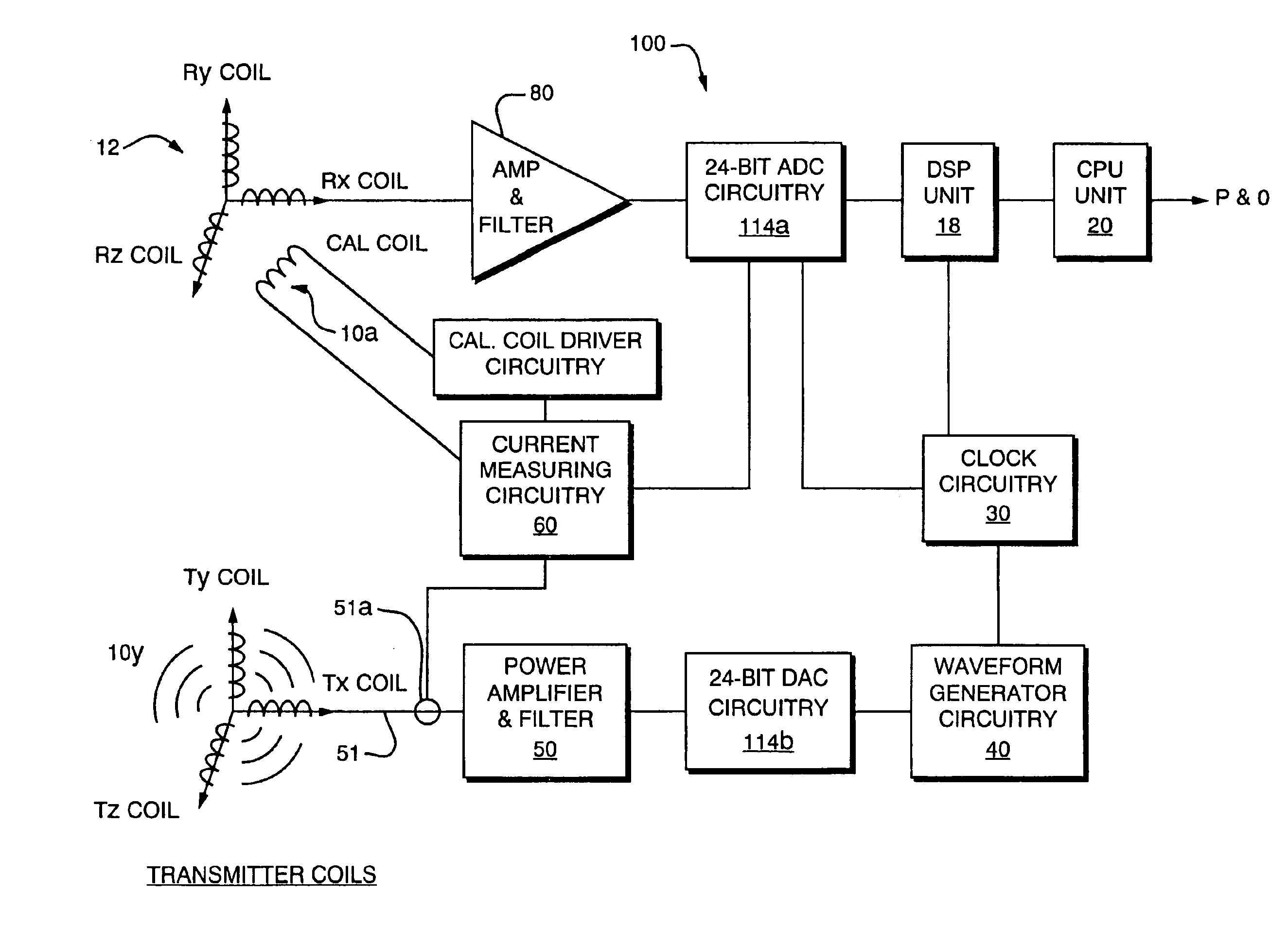
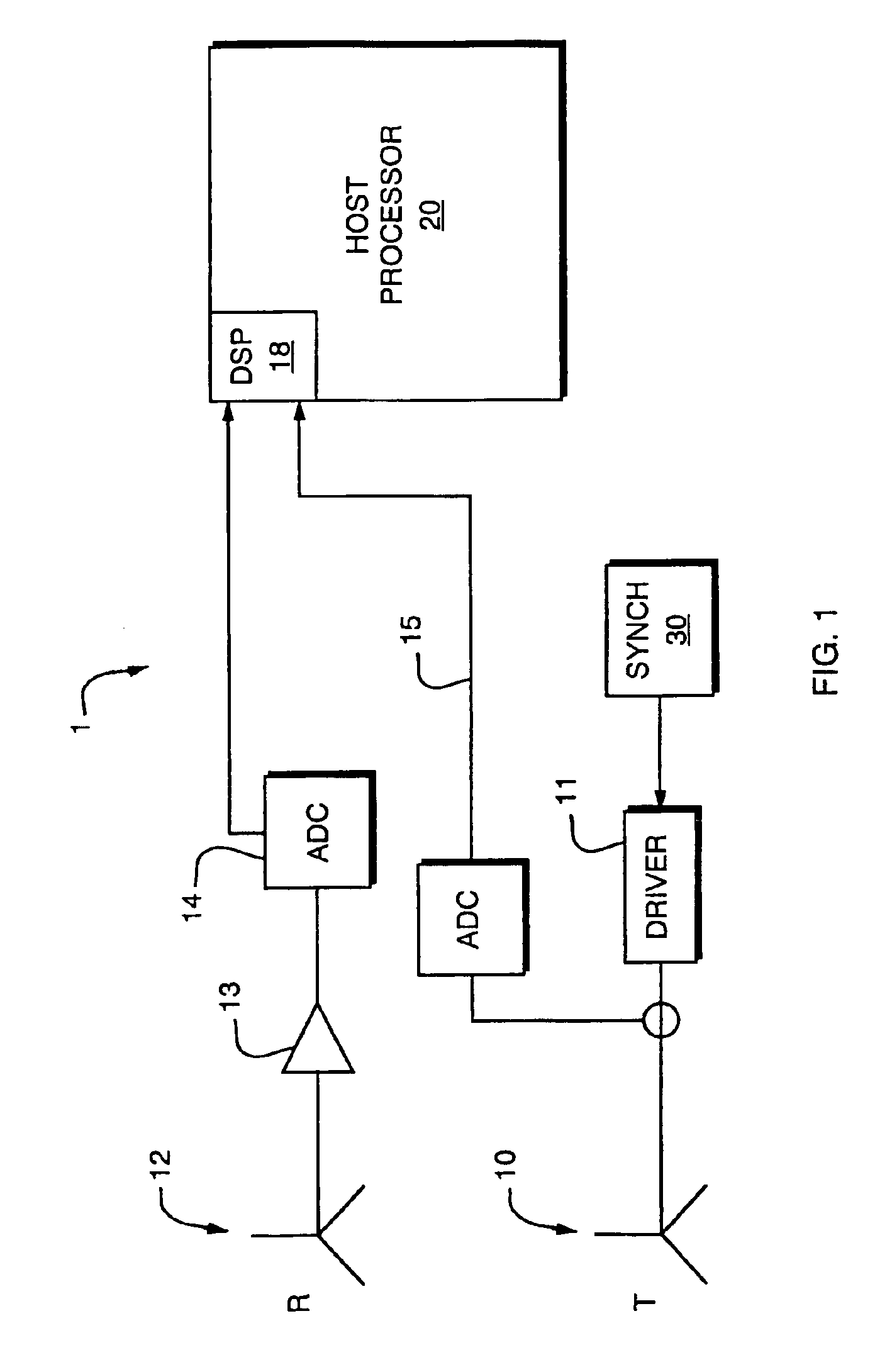
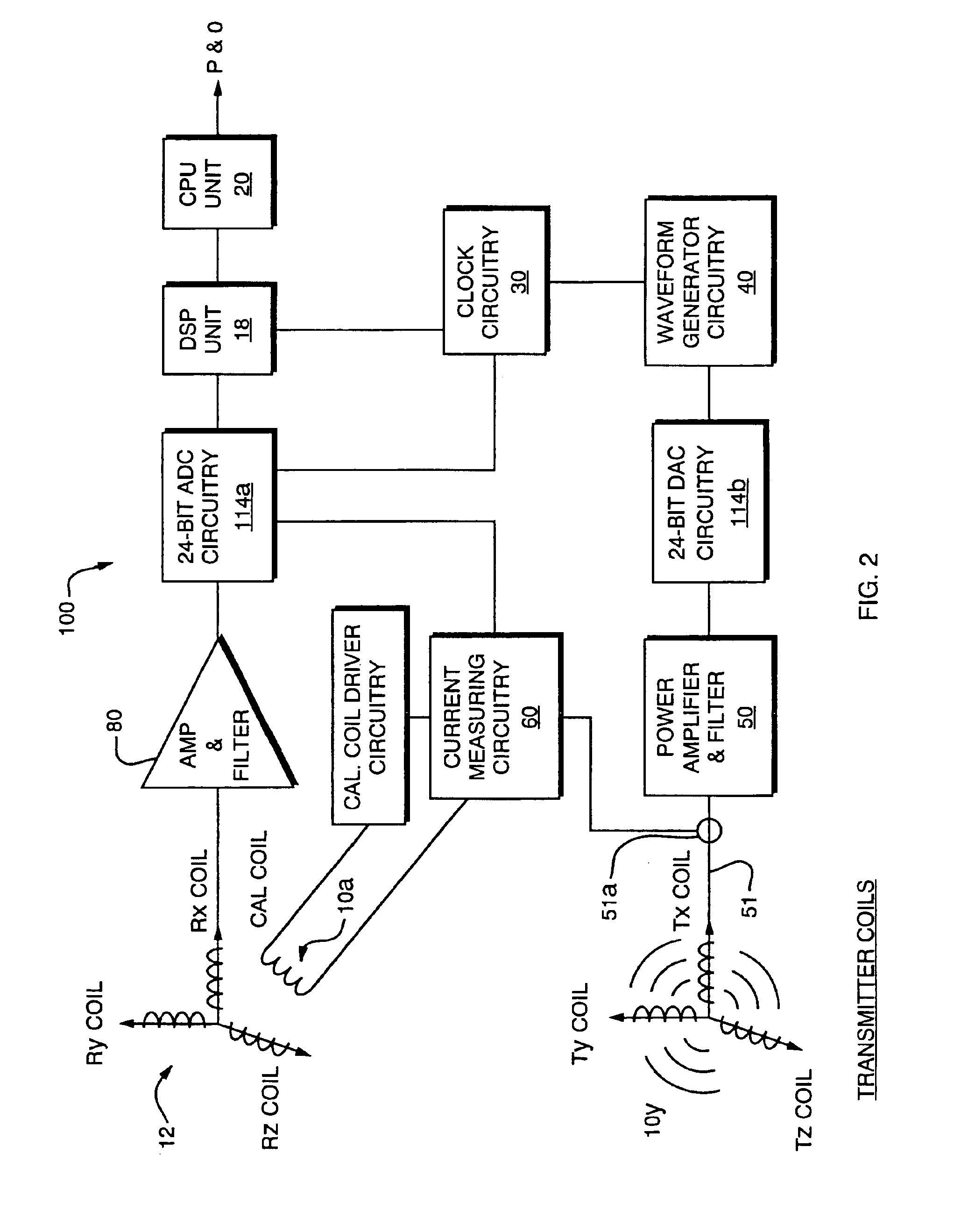
[0032]The present invention is an improved electromagnetic tracking system which may, by way of example, be employed in an operating room or clinical setting to determine the position and orientation of an object such as a catheter, surgical tool, marker or the like in relation to other physical structures, or in relation to images that may, for example, have coordinates assigned thereto by other means, such as via coordinatized 3-D image sets, position-defining frames, or correlation with imaged or tracked fiducials or markers. A great number of such systems are known, being described for example in U.S. Pat. No. 5,967,980 and related patents of M. Ferre et al, U.S. Pat. No. 5,307,072, and others, so the features of such systems will not be further described here.

[0033]As relevant to a first aspect of the present invention, an electromagnetic tracking system includes a magnetic field generator and a magnetic field sensor together with signal conditioning circuitry and a processor f...


PUM


Abstract

The present invention provides an electromagnetic tracking system that includes a field generator and a field sensor arranged to generate and detect, respectively, an electromagnetic field. Both the transmitter and receiver coils are connected to signal conditioning and processing circuitry to provide outputs indicative of the coil signals. A processor operates on the signals to determine the coordinates of the sensing assembly relative to the generator assembly. The signal processor produces ratiometric outputs, and applies a mutual inductance model to solve for position / orientation coordinates. In some embodiments, a disturber in the form of a conductive ring or a sheath is disposed about an interfering piece of equipment to moderate and standardize disturbances due to eddy currents.

Description

RELATED APPLICATIONS[0001]This application is a divisional of U.S. patent application Ser. No. 10 / 108,197, entitled “Magnetic Tracking System,” filed Mar. 27, 2002 now U.S. Pat. No. 6,774,624, which is hereby expressly incorporated by reference in its entirety.BACKGROUND OF THE INVENTION[0002]The present invention relates to magnetic tracking systems of the type wherein a magnetic field is established in a relevant work area, and one or more magnetic field sensors are operated to sense values of a local magnetic field and are processed to determine the position of a tool, instrument or other identified object. In general, such systems operate using a field generating element or assembly, and a field sensing element or assembly, often in conjunction with other position determining elements, such as robotic stepper or optical tracker assemblies to track the relative changes in position between one or more fixed points or structures in the physical environment or associated images, and...

Claims


Application Information

Patent Timeline
Patent Type & Authority Patents(United States)
IPC IPC(8): A61B19/00
CPCA61B5/06A61B19/52A61B19/5244A61B2019/502A61B2019/5238A61B2019/5251A61B2019/5255A61B2019/5268A61B2019/5272A61B2019/5458A61B2034/102A61B90/36A61B2034/2055A61B2034/2068A61B2034/2072A61B34/20A61B2090/376A61B2034/2051A61B2090/3958
Inventor ANDERSON, PETER T.BEAUREGARD, GERALD L.CHERRY, CHRISTOPHER D.
Owner NORTHERN DIGITAL
Why Eureka
Try Eureka