Unmanned air vehicle transmission line docking surveillance

a technology for air vehicles and transmission lines, applied in the direction of arrester hooks, navigation instruments, instruments, etc., can solve the problems of dangerous deployment, inability to meet the needs of passengers,

Inactive Publication Date: 2009-06-09
THE UNITED STATES OF AMERICA AS REPRESETNED BY THE SEC OF THE AIR FORCE
View PDF18 Cites 207 Cited by
  • Summary
  • Abstract
  • Description
  • Claims
  • Application Information

AI Technical Summary

Problems solved by technology

However, such deployment can be dangerous, e.g., inside enemy territory, in fires or other disaster-stricken areas, in areas of toxic spills or leaks, in harsh environments, etc.
Additionally, areas to be monitored may be too remote and thereby make a personnel deployment too impractical or expensive.
The same limitations hold for situations or areas that must be monitored for a longer period of time.
When small unmanned electrical air vehicles are used for these purposes present day limitations in battery technology become rapidly apparent.
As a result of these battery limitations many of the missions that otherwise could be performed by a small unmanned air vehicle are either compromised or regarded as impractical.

Method used


Image

  • Unmanned air vehicle transmission line docking surveillance
  • Unmanned air vehicle transmission line docking surveillance
  • Unmanned air vehicle transmission line docking surveillance

Examples


Embodiment Construction

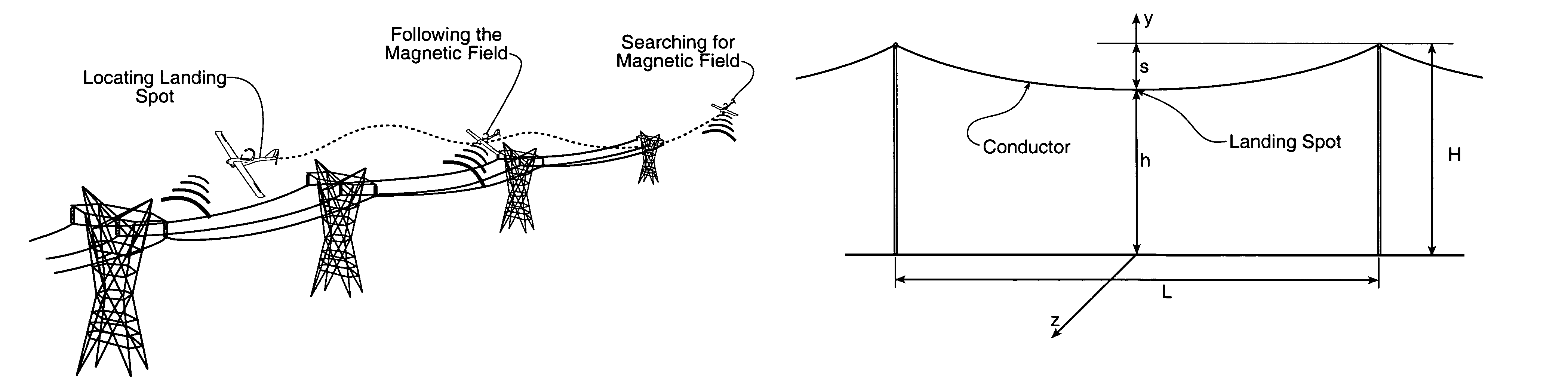
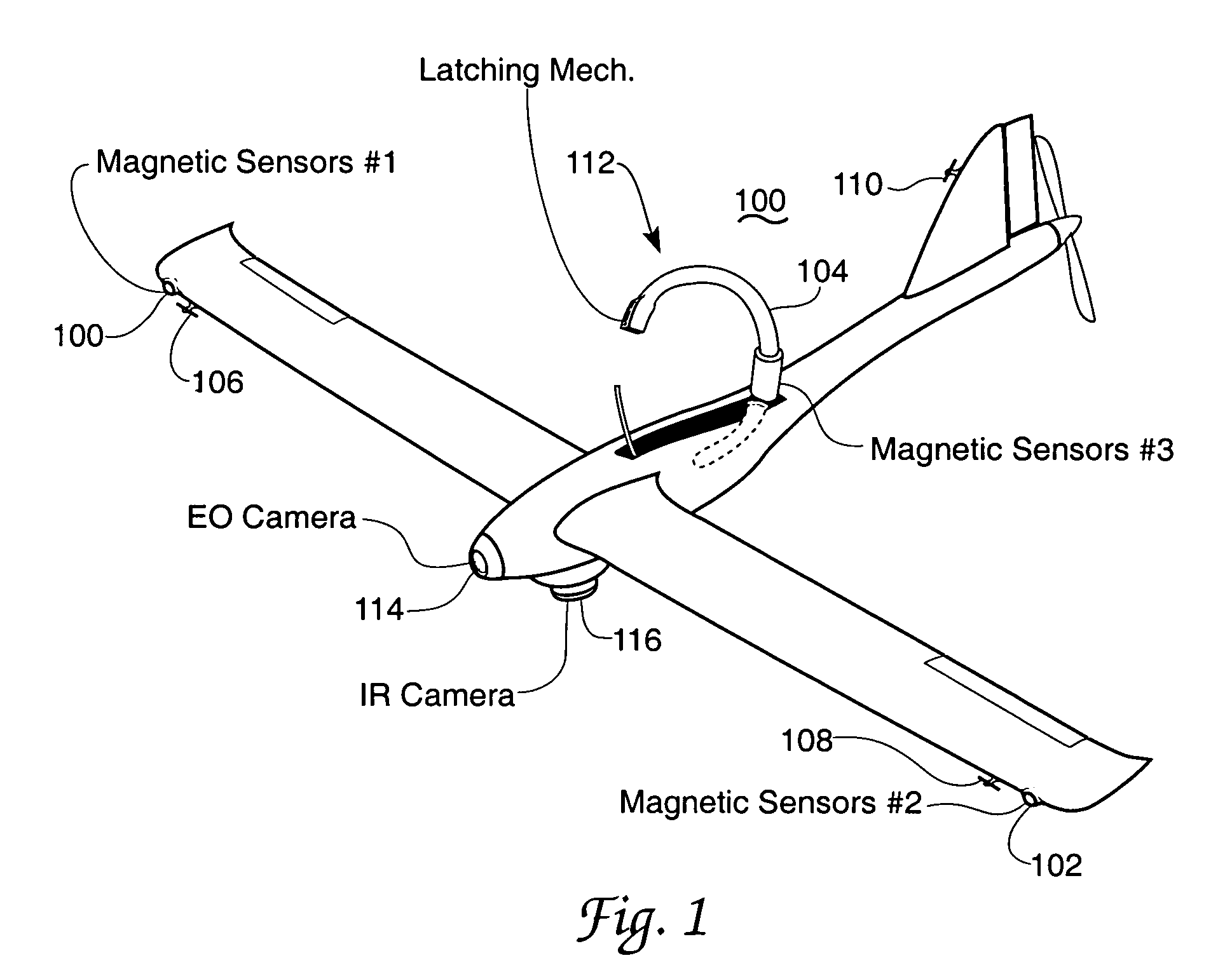
[0031]To achieve accurate navigation, many airborne surveillance systems rely upon the global position system and, particularly, the differential global position system. Until now the global position system has in fact been the main navigation aid for these platforms. The present invention presents an additional supplementary navigation arrangement using electrical transmission lines as an aid to this global position system guidance particularly in terminal portions of a surveillance event. The invention in this document relates generally to the field of control apparatus and more specifically to apparatus for detecting the presence of high voltage high current transmission lines and their use as a navigational aid for dirigible craft such as aircraft, most specifically a small unmanned air vehicle of the electrically propelled type operating in a terminal flight portion. The disclosed guidance arrangement is passive, simple, and effective against known countermeasures.

[0032]The pre...


PUM


Abstract

A small unmanned air vehicle system having autonomous electrical energy transmission line docking capability and especially usable in military or other surveillance situations. Transmission line field sensing by the small unmanned air vehicle is used as an addition to global position system and other navigation methods and is especially applied to vehicle docking maneuvers. A plurality of vehicle carried electromagnetic fields-responsive sensors provides transmission line based signals to the vehicle guidance system in both far field and near field environments. Surveillance sensors are included in the vehicle payload. Vehicle battery charging energy procurement from the transmission line docking is included. Related commonly assigned patent documents are identified.

Description

CROSS REFERENCE TO RELATED PATENT DOCUMENT[0001]The present application is a Continuation in Part of the commonly assigned parent U.S. patent application “POWER LINE SENTRY CHARGING”, Ser. No. 11 / 169,260, filed on 24 Jun. 2005 now U.S. Pat. No. 7,318,564. The contents of this parent application are hereby incorporated by reference herein.[0002]The present document is also somewhat related to the copending and commonly assigned patent document “POWER LINE SENTRY”, Ser. No. 11 / 169,259 also filed on 24 Jun. 2005. The contents of this somewhat related application are hereby incorporated by reference herein.[0003]Each of the Ser. Nos. 11 / 169,259 and 11 / 169,260 documents claims the priority of U.S. Provisional Patent Application 60 / 617,798 filed 4 Oct. 2004.CLAIM OF PRIORITY[0004]This application also claims the benefit of U.S. Provisional Patent Application 60 / 617,798 filed 4 Oct. 2004. The contents of this provisional application are hereby incorporated by reference herein.RIGHTS OF THE...

Claims


Application Information

Patent Timeline
Patent Type & Authority Patents(United States)
IPC IPC(8): G05D1/00B64C13/20
CPCB64C39/024B64C2201/021B64C2201/042H02J7/025B64C2201/127B64C2201/165B64C2201/108B60L2200/10B64U10/25B64U50/19B64U30/20B64U2101/30B64U50/13H02J50/10
Inventor MARSHALL, PATRICK T.ABNER, DOUGLAS M.WILLIAMS, ROBERT
Owner THE UNITED STATES OF AMERICA AS REPRESETNED BY THE SEC OF THE AIR FORCE
Why Eureka
Try Eureka