3-d model based method for detecting and classifying vehicles in aerial imagery

a 3d model and aerial imagery technology, applied in the field of vision systems, can solve the problems of limited 2d methods, inability to leverage the properties of 3d shapes for recognition, and methods that have only been successfully attempted with controlled datasets

Inactive Publication Date: 2012-05-03
SRI INTERNATIONAL
View PDF8 Cites 107 Cited by
  • Summary
  • Abstract
  • Description
  • Claims
  • Application Information

AI Technical Summary

Benefits of technology

[0014]According to an embodiment of the present invention, classifying the detected vehicle further comprises the steps of: forming an N dimensional feature vector of n-scores and p-scores, wherein N is a size of the predetermined plurality of vehicle models; training an N / 2 set of specific vehicle-type SVM classifiers; comparing the detected vehicle to each of the N / 2 trained classifiers; and associating the detected vehicle with a trained classifier which produces the highest confidence value.

Problems solved by technology

A key challenge is to recognize any member in a category of objects despite wide variations in visual appearance due to geometrical transformations, change in viewpoint, or illumination.
Unfortunately 2D methods are limited in that they cannot leverage the properties of 3D shapes for recognition.
Such methods have only been successfully attempted with controlled datasets and with broad classification categories.
A more difficult task is to make classification decisions at a very fine level of distinction, e.g., between different types of vehicles rather than a distinction between the class of vehicles and the class of airplanes.
For such a task, 2D methods that make broad generalizations over object classes with only a coarse utilization of geometric relations are ill suited and 3D models become indispensable.
Unfortunately, this has resulted in mismatches due to faulty edge detection, lack of scene contrast, blurry imagery, scene clutter and noise amongst other factors complicating scene analysis.
Such prior art 3D model based recognition methods have been unable to harness appearance as a rich source of information.
To date, there have been no attempts to accurately simulate scene conditions in the rendered model and to compare rendered models with the actual scene.
Secondly, like 2D approaches, most of the work in prior art 3D models for classification has been geared towards broad categories of objects rather than a finer analysis, in part due to the limitations of employing silhouettes and edges.

Method used


Image

  • 3-d model based method for detecting and classifying vehicles in aerial imagery
  • 3-d model based method for detecting and classifying vehicles in aerial imagery
  • 3-d model based method for detecting and classifying vehicles in aerial imagery

Examples


Embodiment Construction

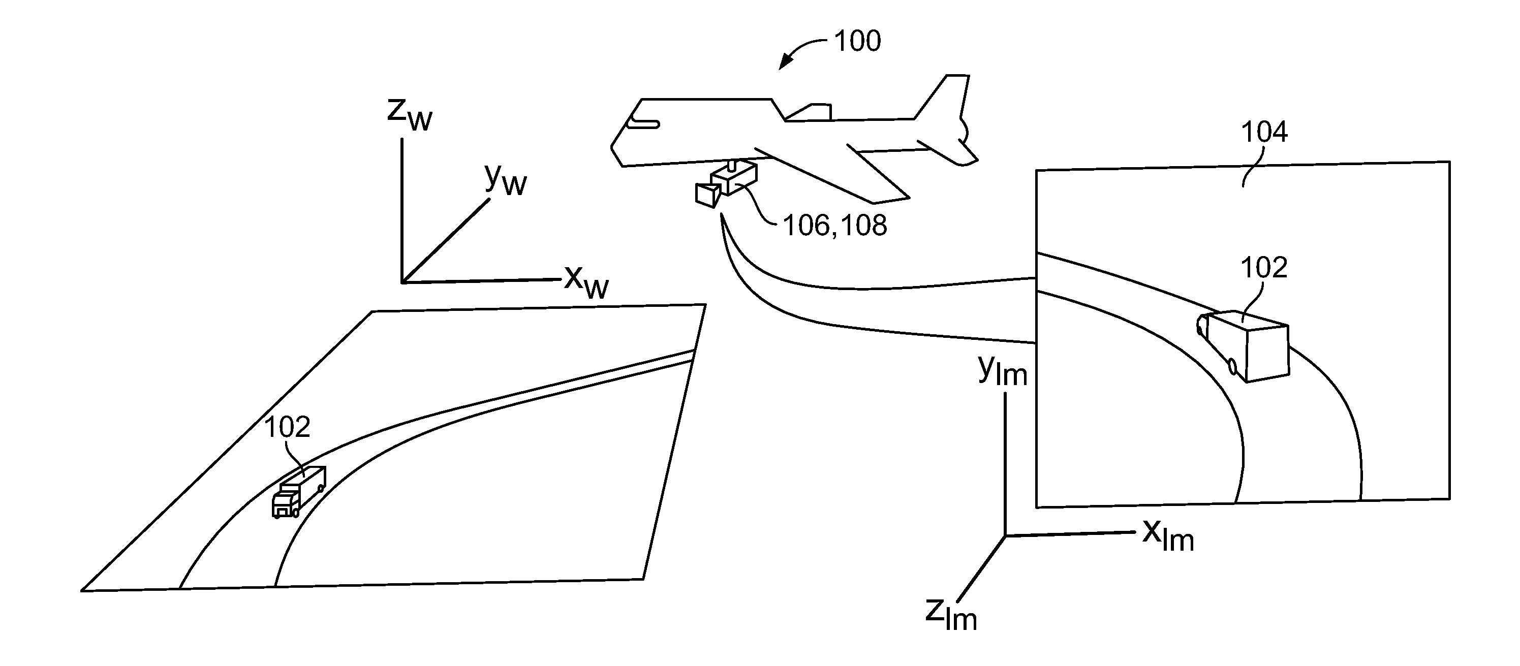
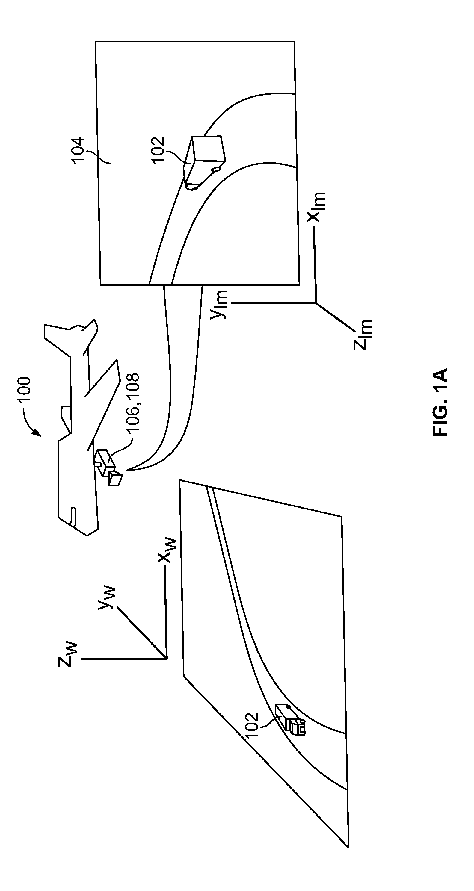
[0035]Embodiments of the present invention employ an exemplary 3D method and system for real-time or near-real-time automatic, unattended detection and classification of types of vehicle models in aerial imagery.

[0036]The term “computer” or “computer platform” is intended to include any data processing device, such as a desktop computer, a laptop computer, a mainframe computer, a server, a handheld device, a digital signal processor (DSP), an embedded processor (an example of which is described in connection with FIG. 2 hereinbelow), or any other device able to process data. The term “communicatively connected” is intended to include any type of connection, whether wired or wireless, in which data may be communicated. The term “communicatively connected” is intended to include, but not limited to, a connection between devices and / or programs within a single computer or between devices and / or separate computers over a network. The term “network” is intended to include, but not limite...


PUM


Abstract

A computer implemented method for determining a vehicle type of a vehicle detected in an image is disclosed. An image having a detected vehicle is received. A number of vehicle models having salient feature points is projected on the detected vehicle. A first set of features derived from each of the salient feature locations of the vehicle models is compared to a second set of features derived from corresponding salient feature locations of the detected vehicle to form a set of positive match scores (p-scores) and a set of negative match scores (n-scores). The detected vehicle is classified as one of the vehicle models models based at least in part on the set of p-scores and the set of n-scores.

Description

CROSS-REFERENCE TO RELATED APPLICATION[0001]This application claims the benefit of U.S. provisional patent application No. 61 / 256,113 filed Oct. 29, 2009, the disclosure of which is incorporated herein by reference in its entirety.GOVERNMENT RIGHTS IN THIS INVENTION[0002]This invention was made with U.S. government support under contract number IARPA NBCHC070062. The U.S. government has certain rights in this'invention.FIELD OF THE INVENTION[0003]The present invention relates generally to vision systems, and more particularly, to a method and a digital processing system for real-time or near-real-time automatic video classification of vehicle model types in aerial imagery.BACKGROUND OF THE INVENTION[0004]The problem of object classification has received considerable attention from both the computer vision and machine learning communities. A key challenge is to recognize any member in a category of objects despite wide variations in visual appearance due to geometrical transformation...

Claims


Application Information

Patent Timeline
Patent Type & Authority Applications(United States)
IPC IPC(8): G06K9/68
CPCG06K9/00651G06K9/00785G06K9/4671G06K9/6282G06K9/6269G06T7/11B64C2201/123B64C39/024G06T7/20G06T2207/10012B64D47/08G06V20/182G06V20/54G06V10/462G06F18/2411G06F18/24323B64U2101/30
Inventor KHAN, SAAD MASOODCHENG, HUIMATTHIES, DENNIS LEESAWHNEY, HARPREET SINGHJUNG, SANG-HACKBROADDUS, CHRISMATEI, BOGDAN CALIN MIHAIDIVAKARAN, AJAY
Owner SRI INTERNATIONAL
Why Eureka
Try Eureka