Unmanned Airborne Vehicle For Geophysical Surveying

an aeromagnetic data and geophysical surveying technology, applied in the direction of navigation instruments, instruments, using reradiation, etc., can solve the problems of limiting the effective reach and range of such surveys, affecting the accuracy of geophysical surveys, so as to facilitate the mapping of remote areas, reduce costs, and eliminate the effect of flight personnel's risk

Inactive Publication Date: 2008-05-29
FUGRO AIRBORNE SURVEYS
View PDF12 Cites 105 Cited by
  • Summary
  • Abstract
  • Description
  • Claims
  • Application Information

AI Technical Summary

Benefits of technology

[0015]Accordingly, the present invention seeks to provide a UAV for aeromagnetic data acquisition, which reduces costs and facilitates t...

Problems solved by technology

A difficulty with this technology is that, at the sensitivities that magnetometers must operate to detect returns from the area under investigation, metal components and electrical and magnetic fields generated by nearby equipment may interfere with the magnetometer readings.
Furthermore, such aircraft require large take-off and landing surfaces, which may limit the effective reach and range of such surveys.
Nevertheless, because of the weak returns often generated by the formations of interest, the tendency has been towards flying at lower and lower clearances above the ground, and in more remote and difficult access areas of the world.
These safety risks are compounded when the survey crosses open water such as ocean or sea.
As a result, many proposed airborne geophysical surveys have not been proceeded with or abandoned on the basis of unacceptable safety risk in order to achieve the desired survey sensitivity.
Over the past two decades there have been numerous, incremental improvements in aeromagnetic data quality and data processing techniques but nothing that could truly be classed as a significant leap so as to overcome the safety/performance imbalance.
There is little or no sustainable product differentiation between service providers and competition is inevitably reduced to price.
Low barriers to entry allow new competitors to continuously enter the market place—virtually guaranteeing an ongoing oversupply situation, driving prices ever further downward, constantly eroding market share and further compromis...

Method used


Image

  • Unmanned Airborne Vehicle For Geophysical Surveying
  • Unmanned Airborne Vehicle For Geophysical Surveying
  • Unmanned Airborne Vehicle For Geophysical Surveying

Examples


Embodiment Construction

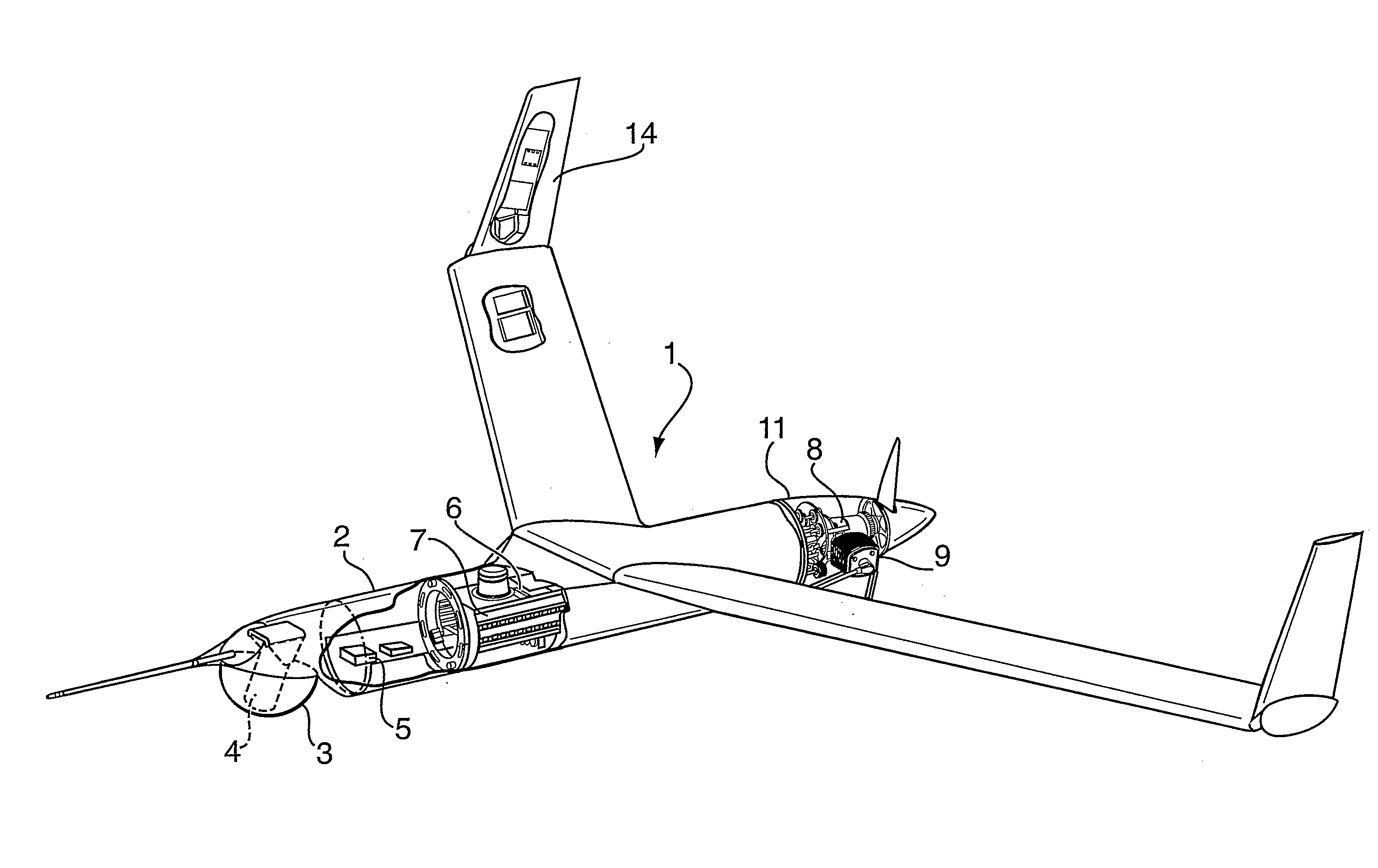
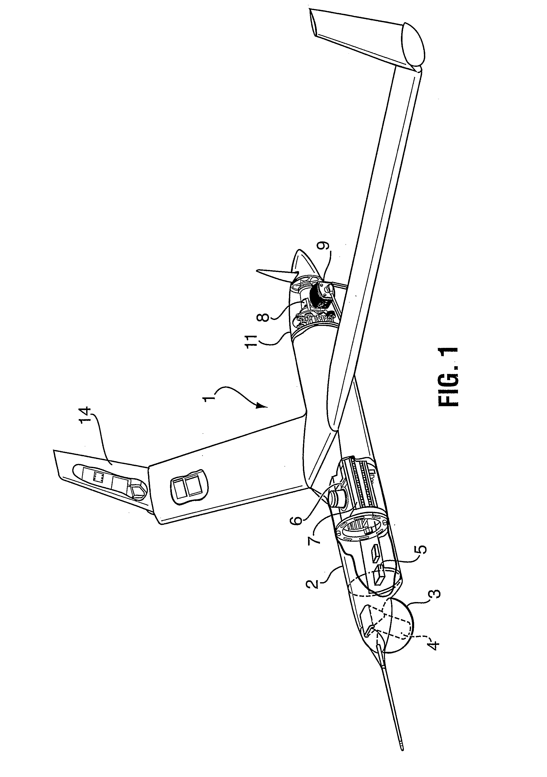
[0041]The invention will be described for the purposes of illustration only in connection with certain embodiments; however, it is to be understood that other objects and advantages of the present invention will be made apparent by the following description of the drawings according to the present invention. While a preferred embodiment is disclosed, this is not intended to be limiting. Rather, the general principles set forth herein are considered to be merely illustrative of the scope of the present invention and it is to be further understood that numerous changes may be made without straying from the scope of the present invention.

[0042]Throughout the description, only the UAV components pertinent to the present invention are discussed. However, it is understood that the UAV of the present invention includes all other components that are required for a UAV to be operational and that a person of ordinary skill in the relevant art would readily know how to select those according t...


PUM


Abstract

An un-manned airborne vehicle (UAV), for acquiring aeromagnetic data for geophysical surveying at low altitude on land or over water, comprising an extended fuselage that is adapted to hold and maintain magnetometer and a magnetic compensation magnetometer at a minimum distance from the avionics and propulsion systems of the UAV. The magnetometer measures magnetic anomalies and the magnetic compensation magnetometer measures magnetic responses corresponding to the pitch, yaw and roll of the UAV. A data acquisition system stores and removes the magnetic response measurements from the magnetic anomaly measurements. The data acquisition system also stores a survey flight plan and transmits the same to the avionics system. The generator of the UAV is shielded and the propulsion system is stabilized to reduce magnetic and vibrational noises that can interfere with the operation of the magnetometer.

Description

FIELD OF THE INVENTION[0001]The present invention relates to a system and a method for acquiring aeromagnetic data. More particularly, the present invention relates to an autonomous unmanned airborne vehicle (UAV) for acquiring aeromagnetic data for geophysical surveying.BACKGROUND OF THE INVENTION[0002]In the mineral and petroleum exploration industries, there is an ongoing effort to identify new regions of geological interest. Frequently, geophysical techniques are employed to identify these regions, which may be at tremendous depths beneath the earth's surface or even under the ocean floor.[0003]One promising geophysical technology is magnetic anomaly detection, which uses sensitive magnetometers to detect small changes in residual magnetism that may indicate regions of geophysical significance or anomalies that are at tremendous depths, separated by rock and / or water. A difficulty with this technology is that, at the sensitivities that magnetometers must operate to detect return...

Claims


Application Information

Patent Timeline
IPC IPC(8): G05D1/04G01C23/00G01V3/165B64C39/02G01V3/40G06F19/00
CPCB64C39/024B64C2201/084B64C2201/127B64C2201/182G01V3/165B64C2201/208B64C2201/141B64U70/70B64U2201/10B64U70/30B64U80/86B64U10/25B64C39/02B64U30/10B64D47/00G01V3/16G01V3/40B64U2101/30
Inventor MILES, PHILIP JOHNPARTNER, RICHARD THOMASKEELER, KENNETH RONALDMCCONNELL, TERENCE JAMES
Owner FUGRO AIRBORNE SURVEYS
Why Eureka
Try Eureka