
Freight transport cableway hanger for transmission lines

A technology for freight cableways and power transmission lines, which is applied in the direction of cable railways, railway vehicles, transportation and packaging, etc. It can solve problems such as construction accidents, rope jumping out, hangers that cannot swing slightly with the ropes, etc., and achieve the effect of reducing construction accidents

Active Publication Date: 2011-10-19
CHINA ELECTRIC POWER RES INST +1
View PDF7 Cites 4 Cited by
  • Summary
  • Abstract
  • Description
  • Claims
  • Application Information

AI Technical Summary

Problems solved by technology

However, since the hanger cannot rotate in the plane of the bracket, when the rope is subjected to external forces such as wind, the hanger cannot swing slightly with the rope, which will easily cause the rope to jump out of the saddle and pulley, causing construction accidents

Method used


Image

  • Freight transport cableway hanger for transmission lines
  • Freight transport cableway hanger for transmission lines
  • Freight transport cableway hanger for transmission lines

Examples


Embodiment 1

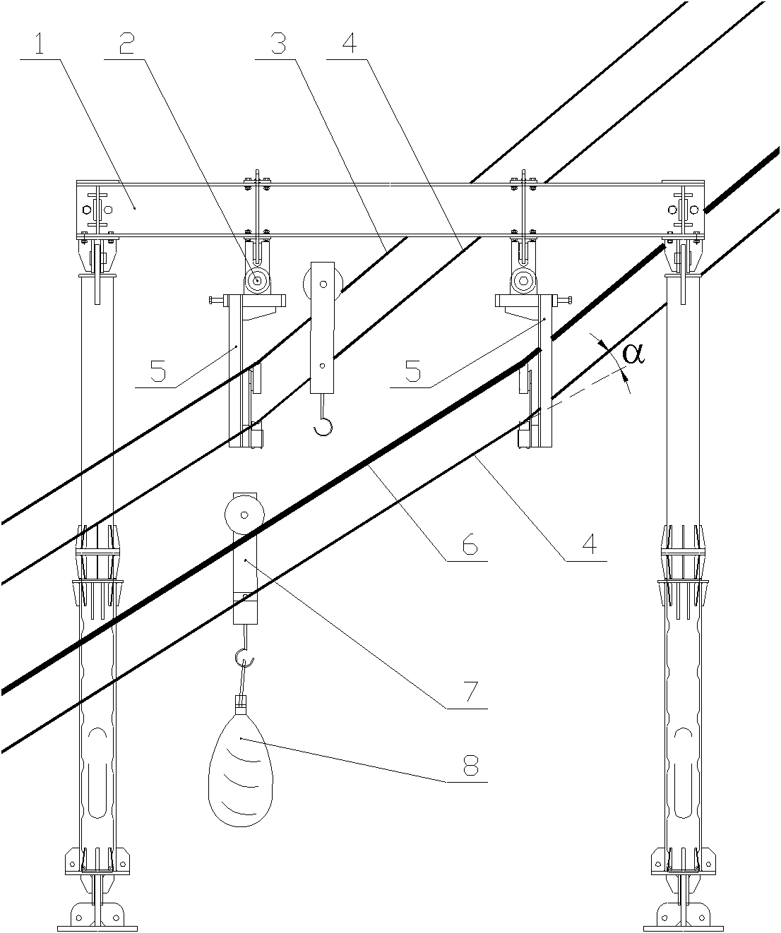
[0027] figure 1 Schematic diagram for the use of freight ropeway racks for transmission lines. When the power transmission line freight cableway is in operation, the bracket is mainly composed of cableway bracket 1, return cable 3, circulating traction cable 4, adjustable cableway hanger 5, load cable 6, running trolley 7, material 8 and other parts. During construction, the cableway support 1 is fixed on the ground, the adjustable cableway hanger 5 is connected with the cableway support 1 through the pin shaft 2, and the return cable 3 and the carrying cable 6 are hung on the support saddle 15 of the adjustable cableway hanger 5 In the groove, the circulating traction cable 4 is hung on the cable wheel 16 of the adjustable cableway hanger 5, the running wheel of the unloaded running trolley 7 walks on the return cable 3, and the running trolley 7 carrying the material 8 Walking on the carrying cable 6, the running trolley 7 is connected and fixed with the circulating tractio...

Embodiment 2

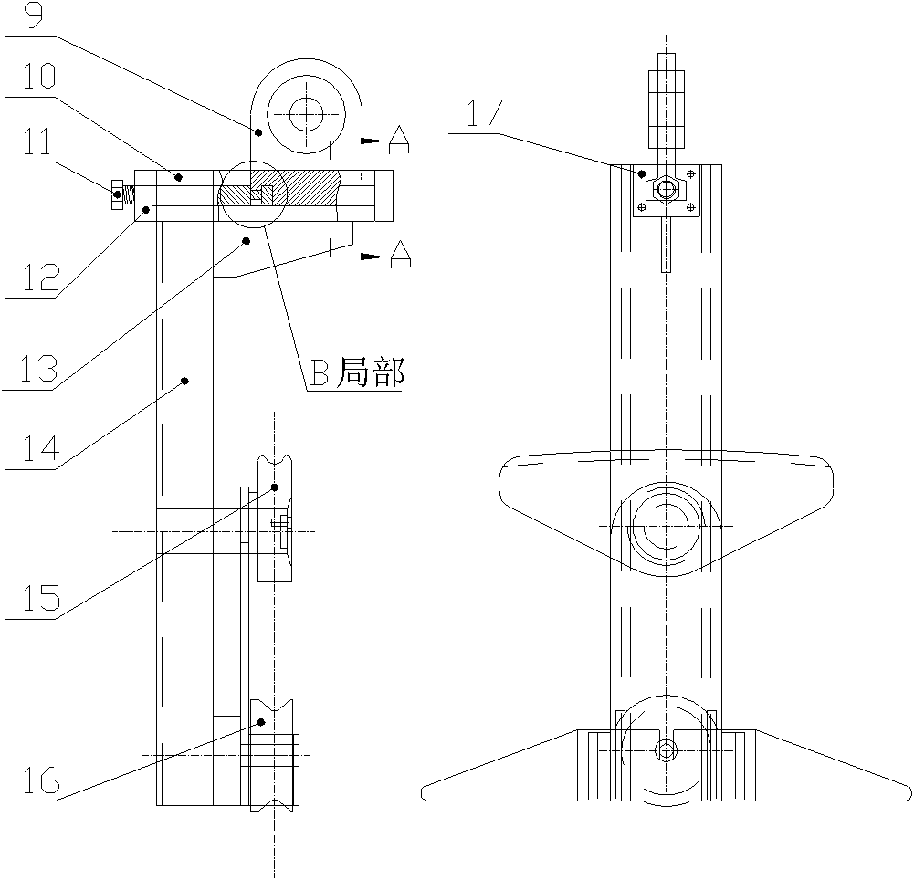
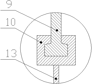
[0029] figure 2 It is a structural schematic diagram of the adjustable cableway hanger. The adjustable cableway hanger 5 mainly includes a hanging plate 9, an adjusting bolt 11, an end plate 12, a reinforcing plate 13, a spreader body 14, a saddle 15, a cable wheel 16 and a fixing bolt 17, and the end plate 12 is provided with a chute 10. Hanger body 14 is vertically arranged with end plate 12, and reinforcing plate 13 is set at the junction of hanging tool body 14 and end plate 12, and the purpose of reinforcing plate 13 setting is to strengthen the connection strength of hanging tool body 14 and end plate 12. The rope saddle 15 and the rope wheel 16 are arranged on the same side of the hanger body 14, the rope saddle 15 is located above the rope wheel 16, and its setting position is on the same side of the hanger body 14 as the hanging plate 9. The upper end surfaces of the cable saddle 15 and the cable wheel 16 are in the shape of grooves. During construction, the load-b...


PUM


Abstract

The invention provides a freight transport cableway hanger for transmission lines, and belongs to the technical field of the construction of transmission lines. The hanger is suitable for engineering freight transport ropeways for the transmission lines, and can prevent ropes from dropping effectively by adjusting angles with the ground at complex terrains to reduce engineering accidents caused by the dropped ropes. The hanger mainly comprises a hanger body, an end plate which is perpendicular to the hanger body, a hanging plate, an adjustable bolt, a rope support saddle and a rope support wheel, wherein a sliding chute is formed on the end plate; the hanging plate can slide along the sliding chute of the end plate by the adjustment of the adjustable bolt; and the hanging plate of the hanger is connected with the ropeway support by a pin shaft. The hanger has an adjustable function, and when the ropes of a ropeway meet intersection angles at the support, the hanger can regulate the position of the hanging plate, so that the hanger is perpendicular to the ground without external assistance. Simultaneously, the hanger has can swing with the ropes of the ropeway slightly, so that rope dropping accidents are avoided.

Description

technical field [0001] The invention belongs to the technical field of overhead cableway components for transporting goods on power transmission lines, and in particular relates to a freight cableway hanger for power transmission lines. Background technique [0002] With the development of power line construction, overhead transmission lines will inevitably pass through hilly and mountainous areas, and the mountainous terrain is complex and changeable. During the construction process, the transportation of materials required for the tower foundation and tower materials is very prominent. In the past circuit construction in the power substation industry, the method of building vehicle transportation access roads was generally adopted. Building vehicle transport access roads requires a lot of manpower and material resources, felling a lot of trees, and moving a lot of earth and stones. When it is impossible to build a vehicle access road, it has to be carried manually. The la...

Claims


Application Information

Patent Timeline
Patent Type & Authority Applications(China)
IPC IPC(8): B61B7/00B61B12/02
Inventor 江明缪谦
Owner CHINA ELECTRIC POWER RES INST
Learn More