Weight compensation device on underframe of elevator carriage

The technology of a compensation device and a car bottom frame is applied in elevators, transportation and packaging, elevators and other directions in buildings, which can solve the problems of inability to apply balance iron or counterweight block installation and fixation, and limited range of car weight compensation. To achieve the effect of convenient installation and fixation, reducing wear and tear, and large compensation range

Inactive Publication Date: 2011-10-19
三六零安全科技股份有限公司
View PDF8 Cites 5 Cited by
  • Summary
  • Abstract
  • Description
  • Claims
  • Application Information

AI Technical Summary

Problems solved by technology

[0003] On the elevator, the existing car bottom frame 1' usually adopts a steel pipe with a C-shaped cross section, such as figure 1 As shown, the existing weight compensating device includes a balance iron 2' with a groove on the side, the car bottom frame 1' is inserted in the groove, and the C-shaped opening 3' faces outward, as figure 1 and 2 As shown, there are perforations on the corresponding parts of the balance iron 2' and the car underframe 1', and bolts 4' pass through the holes. The C-shaped opening 3' of 'can screw the nut 5' on the threaded body of the bolt 4' passing through the car bottom frame 1', and the bolt 4' and the nut 5' are hidden in the steel pipe of the car bottom frame 1'. The balance iron 2' is fixed on the car bottom frame 1', and the balance iron 2' acts as a counterweight. The weight of the car is compensated by increasing or decreasing the number of the balance iron 2', so as to balance the center of gravity of the car and reduce the weight of the car. However, the range of compensation for the weight of the car through the balance iron is limited, and if the car bottom frame adopts a steel pipe with a rectangular cross section, the above method cannot be applied to the installation and fixation of the balance iron or the counterweight

Method used


Image

  • Weight compensation device on underframe of elevator carriage
  • Weight compensation device on underframe of elevator carriage
  • Weight compensation device on underframe of elevator carriage

Examples


Embodiment Construction

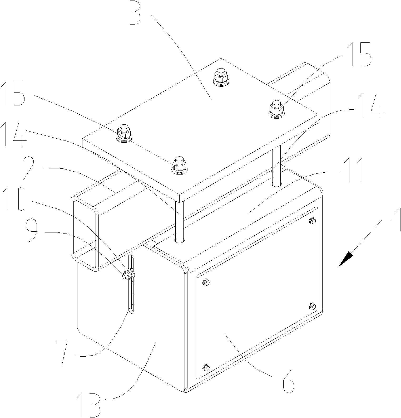
[0017] The structure of the present invention will be further described below in conjunction with the accompanying drawings.

[0018] see Figure 3-4 As shown, the weight compensating device on the elevator car chassis includes a car chassis 2, a box body 1 with an inner cavity 16, an opening 5 communicated with the inner cavity 16 provided on the box body 1, and the opening 5 can be detachably covered. The cover plate 6, the counterweight 4 can be placed in the inner cavity 16 of the box body 1, the size of the opening 5 should be able to allow the counterweight 4 to pass through, and the box body 1 can clamp the car floor separately by cooperating with the connecting plate 3 Rack 2. Place a plurality of counterweights 4 in the box body 1, and the box body 1 and the connecting plate 3 cooperate to clamp the car frame 2, so as to realize the connection of the box body 1 equipped with a plurality of counterweights 4 on the car bottom frame 2 fixed, so that the weight of the c...


PUM


Abstract

The invention discloses a weight compensation device on an underframe of an elevator carriage. Multiple balance weight blocks are arranged in a box body, the box body is matched with a connecting plate to clamp the underframe of the carriage, and the box body provided with multiple balance weight blocks is connected and fixed on the underfame of the carriage, thus the weight of the carriage can be compensated, the forward-backward gravity of the carriage is balanced, and abrasion of a guide shoe to the carriage is reduced, the balance weight blocks in an inner cavity can be increased or decreased by virtue of an opening of the box body, and the box body is matched with a connecting block to clamp the underframe of the carriage and be separated from the underframe of the carriage, thus the box bodies can be increased or decreased on the underframe of the carriage, the compensation range on the weight of the carriage is wider, and the forward-backward gravity of the carriage can be better balanced. The box body is fixed on the underframe by the way that the box body is matched with the connecting plate to clamp the underframe of the carriage, thus the box body can be conveniently mounted and fixed no matter the underframe of the carriage adopts a steel tube with a C-shaped cross section or the steel tube with a rectangular cross section, namely the balance weight blocks are mounted and fixed on the underframe of the carriage.

Description

[0001] technical field [0002] The invention relates to a weight compensating device on an elevator car bottom frame. Background technique [0003] On the elevator, the existing car bottom frame 1' usually adopts a steel pipe with a C-shaped cross section, such as figure 1 As shown, the existing weight compensating device includes a balance iron 2' with a groove on the side, the car bottom frame 1' is inserted in the groove, and the C-shaped opening 3' faces outward, as figure 1 and 2 As shown, there are perforations on the corresponding parts of the balance iron 2' and the car underframe 1', and bolts 4' pass through the holes. The C-shaped opening 3' of 'can screw the nut 5' on the threaded body of the bolt 4' passing through the car bottom frame 1', and the bolt 4' and the nut 5' are hidden in the steel pipe of the car bottom frame 1'. The balance iron 2' is fixed on the car bottom frame 1', and the balance iron 2' acts as a counterweight. The weight of the car is c...

Claims


Application Information

Patent Timeline
Patent Type & Authority Applications(China)
IPC IPC(8): B66B11/02B66B7/00B66B17/12
Inventor 倪镭朱顺周卫东谢琛陆伟王春光
Owner 三六零安全科技股份有限公司
Why Eureka
Try Eureka