
Light source seat

A technology of light source seat and optical fiber, applied in the field of light source seat

Inactive Publication Date: 2011-10-19
SHANGHAI RUIYIN ELECTRONICS TECH
View PDF4 Cites 0 Cited by
  • Summary
  • Abstract
  • Description
  • Claims
  • Application Information

AI Technical Summary

Problems solved by technology

[0003] The purpose of the present invention is to provide a key component on the steel ball surface trace detector - the light source seat, to solve the problem of collecting steel ball surface traces in the steel ball surface trace detection

Method used


Image

  • Light source seat
  • Light source seat
  • Light source seat

Examples


Embodiment Construction

[0009] The present invention will be further described below in conjunction with accompanying drawing.

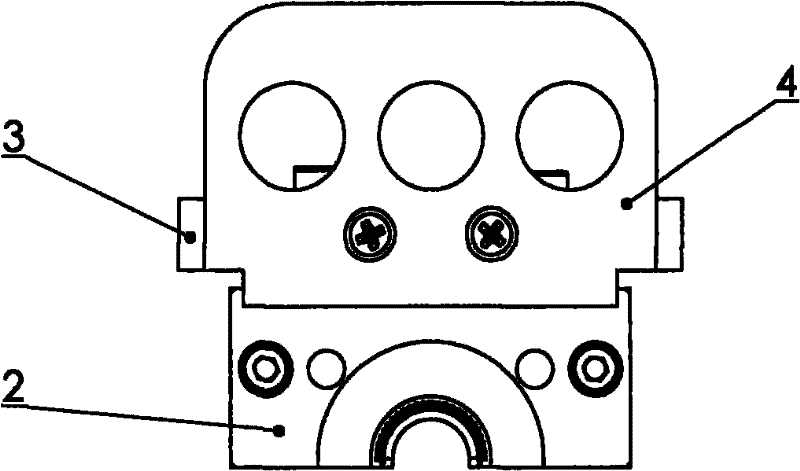
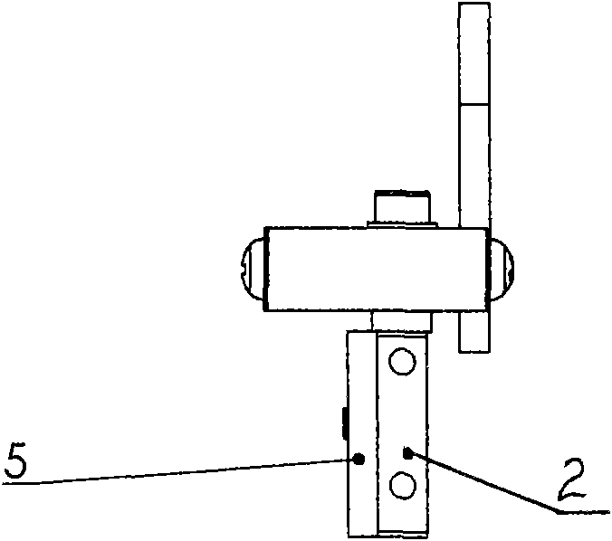
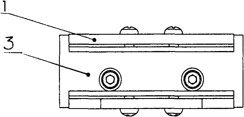
[0010] Such as figure 1 , figure 2 , image 3 Shown: the light source holder of the present invention comprises front pressure plate 1, rear pressure plate 4, optical fiber frame 3, optical fiber transmitting seat 5 and optical fiber receiving seat 2, and wherein front pressure plate 1 is connected and fixed with optical fiber frame 3 by screw, and optical fiber frame 3 is connected and fixed by screw The optical fiber receiving seat 2 is connected, the rear pressure plate 4 is connected with the optical fiber frame 3 through screws, and the optical fiber transmitting seat 5 is connected with the optical fiber receiving seat 2 through screws. On the same end face of the fiber emitting seat 5 and the fiber receiving seat 2, there are holes with the same radius and an arc-shaped slope, and fiber holes are evenly distributed along the circumference on the inner wall of the ...


PUM


Abstract

The invention discloses a light source seat which is used for solving the problem of the collecting of the surface trace of a steel ball in the process of detecting the surface trace of the steel ball. The light source seat disclosed by the invention comprises a front press plate, a rear press plate, an optical fiber frame, an optical fiber receiving seat and an optical fiber emitting seat, wherein the optical fiber frame is respectively connected with and fixed on the front press plate, the optical fiber receiving seat and the rear press plate through screws; the optical fiber receiving seat and the optical fiber emitting seat are connected and fixed together through screws; holes which have the same radius and are provided with circular arc inclined planes are arranged on the same end surface of the optical fiber receiving seat and the optical fiber emitting seat; and optical fiber holes are uniformly distributed on the inner wall of the each hole along the circumference. The light source seat disclosed by the invention is mainly used for the detector for detecting the surface trace of a steel ball.

Description

technical field [0001] The invention relates to a light source seat, in particular to a light source seat on a steel ball surface trace detector. Background technique [0002] Steel balls are important accessories for bearing companies, and the quality of steel balls is directly related to quality issues such as the accuracy, performance and life of bearings. my country is a big producer of steel balls in the world, but there is a big gap between the quality and advanced countries in the world. The main reasons are: first, the quality problems of steel ball grinding machines; second, the problems of steel ball surface trace detection and sorting. The domestic steel ball production industry still adopts the manual grading method of naked eye sorting. This method has the following problems: 1. Large randomness and large errors, which are prone to missed judgments and misjudgments, resulting in poor quality stability of steel balls; 2. The labor intensity is high, and it is ea...

Claims


Application Information

Patent Timeline
IPC IPC(8): G01N21/01
Inventor 龚鼎新徐军沈正芳
Owner SHANGHAI RUIYIN ELECTRONICS TECH
Learn More