

Hydraulic vertical-type conveying device
A conveying device, vertical technology, applied in the field of hydraulic vertical conveying device, can solve the problem of insufficient public perception, etc., and achieve the effect of reasonable overall structure
- Summary
- Abstract
- Description
- Claims
- Application Information
AI Technical Summary
Problems solved by technology
Method used
Image

Examples
Embodiment Construction
[0018] In order to enable the examiners of the patent office, especially the public, to understand the technical essence and beneficial effects of the present invention more clearly, the applicant will describe in detail the following in the form of examples, but none of the descriptions to the examples is an explanation of the solutions of the present invention. Any equivalent transformation made according to the concept of the present invention which is merely formal but not substantive shall be regarded as the scope of the technical solution of the present invention.
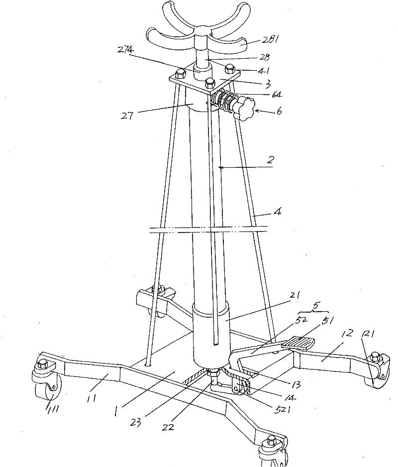
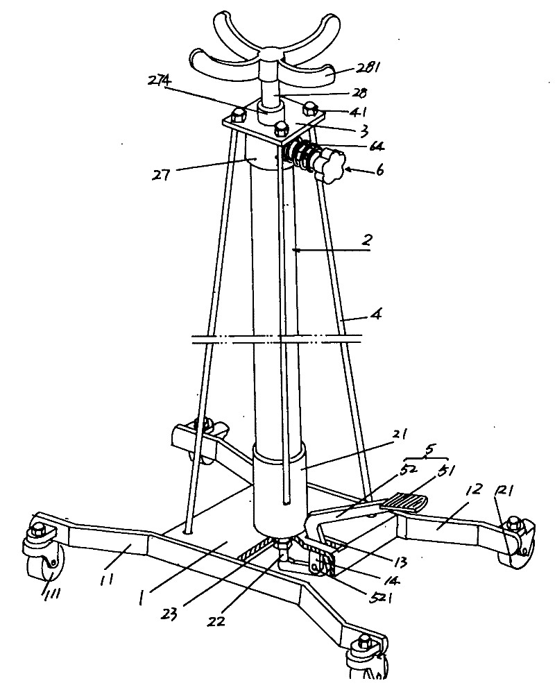
[0019] please see figure 1 , given the fixed base 1, a first roller frame 11 is fixed on one side of the lower fixed base 1, both ends of the first roller frame 11 protrude from the lower fixed base 1 and each pivot is provided with a first roller 111 ; a second roller frame 12 is fixed on the other side of the lower fixing seat 1 , both ends of the second roller frame 12 protrude from the lower fixing seat 1...
PUM
 Abstract
Description
Claims
Application Information