Body structure of boiling rotating fluidized bed

A fluidized bed and bed technology, used in hearth furnaces, drying solid materials, heating to dry solid materials, etc., can solve the problem of large moving resistance at the bottom of the boiling layer, high preparation and maintenance costs, and fluidized bed. It can solve the problems of complex structure and other problems, so as to achieve the effect of optimizing the effect of humidity adjustment and drying, improving the effect of humidity adjustment and drying, and achieving good economic and social benefits.

Active Publication Date: 2011-11-02
长沙通发高新技术开发有限公司
View PDF13 Cites 17 Cited by
  • Summary
  • Abstract
  • Description
  • Claims
  • Application Information

AI Technical Summary

Problems solved by technology

However, the surface of the existing fluidized bed body is provided with various protruding injectors, which leads to unevenness of the bed surface of the fluidized bed. Although the fluidized movement of the material layer can be realized, the movement resistance at the bottom of the boiling layer is relatively large. , there is a dead corner of material storage in the low concave, which is easy to cause the gas injection hole to be blocked, and the structure of the whole fluidized bed body is complicated, and the preparation cost and maintenance cost are high

Method used


Image

  • Body structure of boiling rotating fluidized bed
  • Body structure of boiling rotating fluidized bed
  • Body structure of boiling rotating fluidized bed

Examples


Embodiment 1

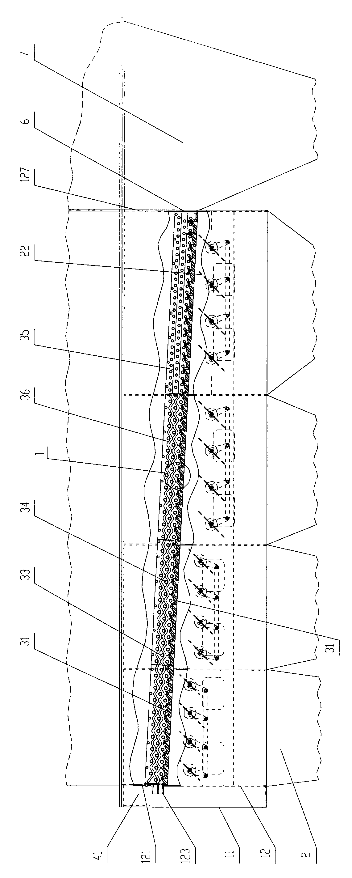
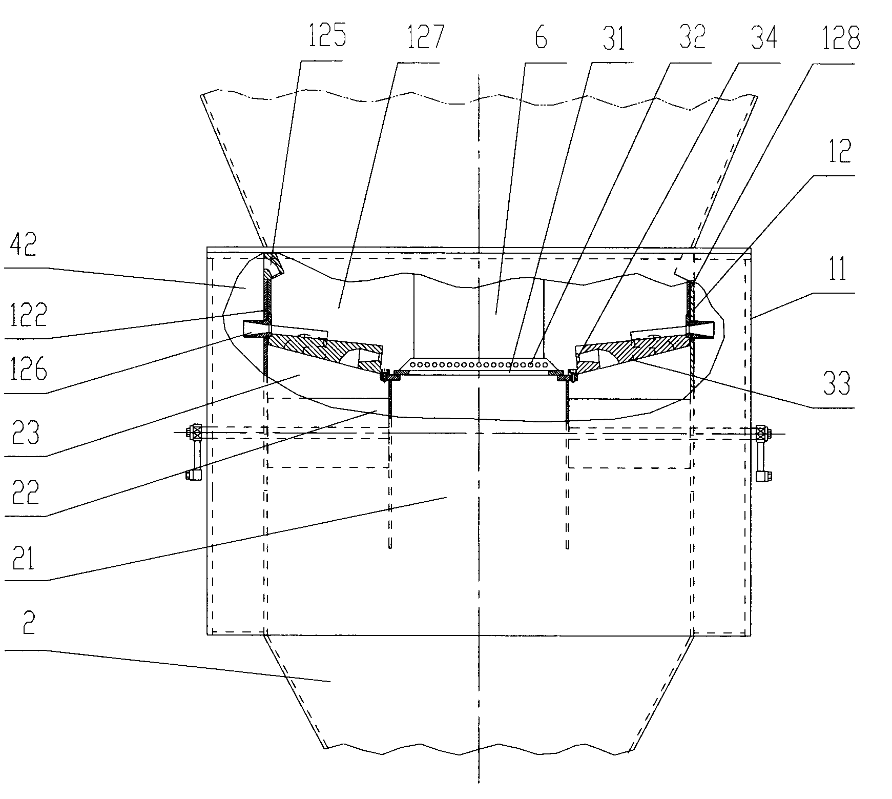
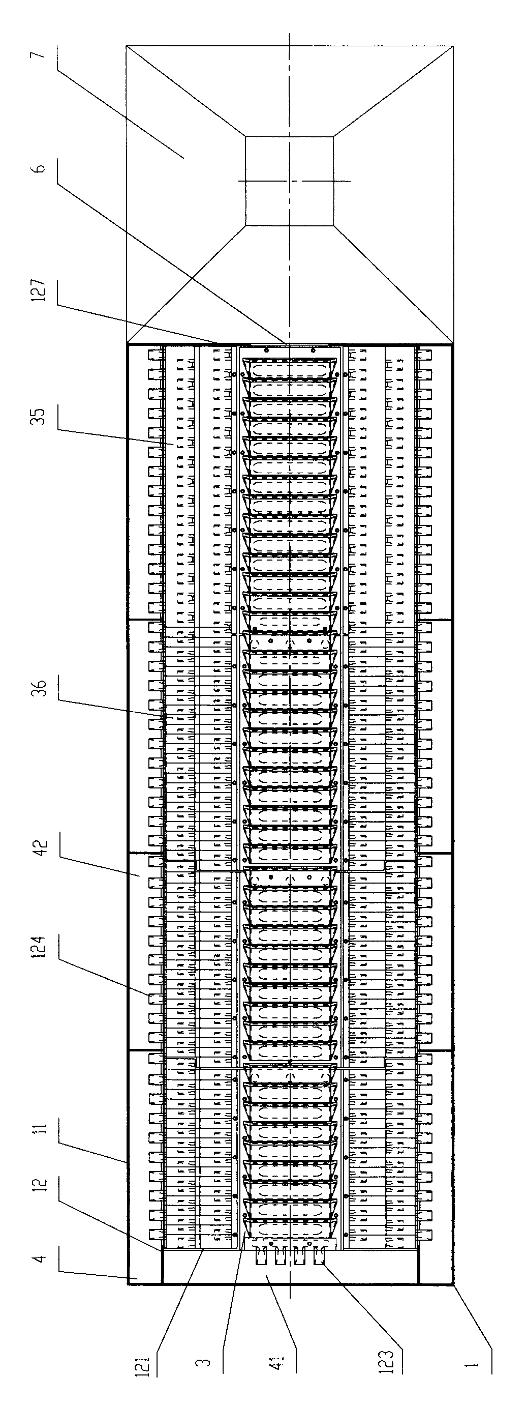
[0025] a kind of like Figure 1 ~ Figure 3 The bed structure of the shown boiling swirling fluidized bed of the present invention includes an outer shell 1 and an air distribution plate 3, and the outer shell 1 and the air distribution plate 3 are covered to form a fluidized bed cavity; the air distribution plate 3 is concave. Groove-shaped and inclined from the feed end of the bed to the discharge end, the air distribution plate 3 is mainly composed of the air distribution bottom plate 31 in the middle and the air distribution side plates 33 on both sides. The segmented air chamber 2 of the fluidized bed (the segmented air chamber of the boiling swirling fluidized bed generally includes the main air chamber 21, the side air chamber 23, and the air volume and pressure regulating door 22 and other components) connected to the air injection bottom hole 32, The air distribution side plate 33 is provided with an air injection side hole 34 communicating with the segmental air chamb...

Embodiment 2

[0032] a kind of like Figure 5 ~ Figure 8 The bed structure of the shown boiling swirling fluidized bed of the present invention is basically the same as the fluidized bed structure of embodiment 1, and its difference with embodiment 1 only lies in the following two points: 1) the air distribution side The adjacent upper and lower rows of jet side holes 34 arranged on the plate 33 are all separated by the wave surface 36 on the air distribution side plate 33, and all other components and connection methods are the same as in Embodiment 1; 2) as Figure 8 As shown, in this embodiment, airflow guides (321) are all correspondingly provided on the air distribution bottom plate 31 above each row of air injection bottom holes 32.

Embodiment 3

[0034] a kind of like Figure 9 ~ Figure 12 The bed structure of the shown boiling swirling fluidized bed of the present invention is basically the same as the bed structure of the fluidized bed in Example 1, and the difference with Example 1 is only the following three points: 1) the air distribution side plate 33, the upper and lower rows of air injection side holes 34 are all separated by the flat surface 35 on the air distribution side plate 33; Feed port 6, it is to offer a discharge port 8 connected with the bottom discharge pipe 5 of the fluidized bed at the longitudinal discharge end of the air distribution bottom plate 31, and the fluidized bed of the present embodiment is carried out through the discharge port 8. Discharging; in another specific embodiment, even the rear inner wall discharge opening 6 in embodiment 1 and the discharge opening 8 in the present embodiment can be set at the same time; 3) as Figure 12 As shown, the air distribution bottom plate 31 abov...


PUM


Abstract

The invention discloses a body structure of a boiling rotating fluidized bed, which comprises an outer housing and an air distributor. Due to the coverage of the outer housing and the air distributor, an accommodation chamber of the fluidized bed is formed. The air distributor is like a groove and tilts from the feeding end of the bed body to the discharging end. The air distributor mainly comprises an air distributor bottom board configured in the middle and air distributor sideboards configured on the two sides. A blowing bottom hole communicated with a sectionalized wind box is configured on the air distributor bottom board, and a blowing side hole communicated with the sectionalized wind box is configured on the air distributor sideboard. The air distributor is tooth-shaped or wave-shaped, the blowing bottom hole is configured between the teeth of a tooth-shaped air distributor bottom board or at the wave trough of a wave-shaped air distributor bottom board, and the opening of the blowing bottom hole faces the discharging end of the bed body. The opening of the blowing side hole on the air distributor sideboard faces the air distributor bottom board. The invention has the advantages of simple body structure, smooth bed surface and optimized flow field and can greatly improve the boiling rotating fluidized status. In addition, the invention can reduce more energy consumption.

Description

technical field [0001] The invention relates to a component part of a fluidized bed, in particular to a bed body structure of the fluidized bed. Background technique [0002] The bed structure of the existing boiling swirling fluidized bed is in the shape of an inverted trapezoidal shallow groove (see Chinese patent documents such as CN101629775A, CN101709913A, CN101708493A), and is inclined from front to back. Elbow gas injectors arranged in staggered rows, and multiple rows of gas injectors with cone heads arranged in staggered rows are arranged on the concave plane in the middle. Collect and rise to generate swirling flow, showing boiling swirling fluidization state, so as to achieve the purpose of moderately reducing the humidity of solid particles on the fluidized bed. However, the surface of the existing fluidized bed body is equipped with various protruding injectors, which leads to unevenness of the bed surface of the fluidized bed. Although the fluidized movement o...

Claims


Application Information

Patent Timeline
Patent Type & Authority Applications(China)
IPC IPC(8): F26B3/084
Inventor 阎国俊阎国基
Owner 长沙通发高新技术开发有限公司
Why Eureka
Try Eureka