Bed structure of boiling swirling fluidized bed
A fluidized bed and bed technology, applied in hearth furnaces, drying solid materials, heating to dry solid materials, etc., can solve the problem of high preparation cost and maintenance cost, large moving resistance at the bottom of the boiling layer, fluidized bed It can improve the effect of humidity control and drying, optimize the effect of humidity control and drying, and achieve good economic and social benefits.
- Summary
- Abstract
- Description
- Claims
- Application Information
AI Technical Summary
Problems solved by technology
Method used
Image
Examples
Embodiment 1
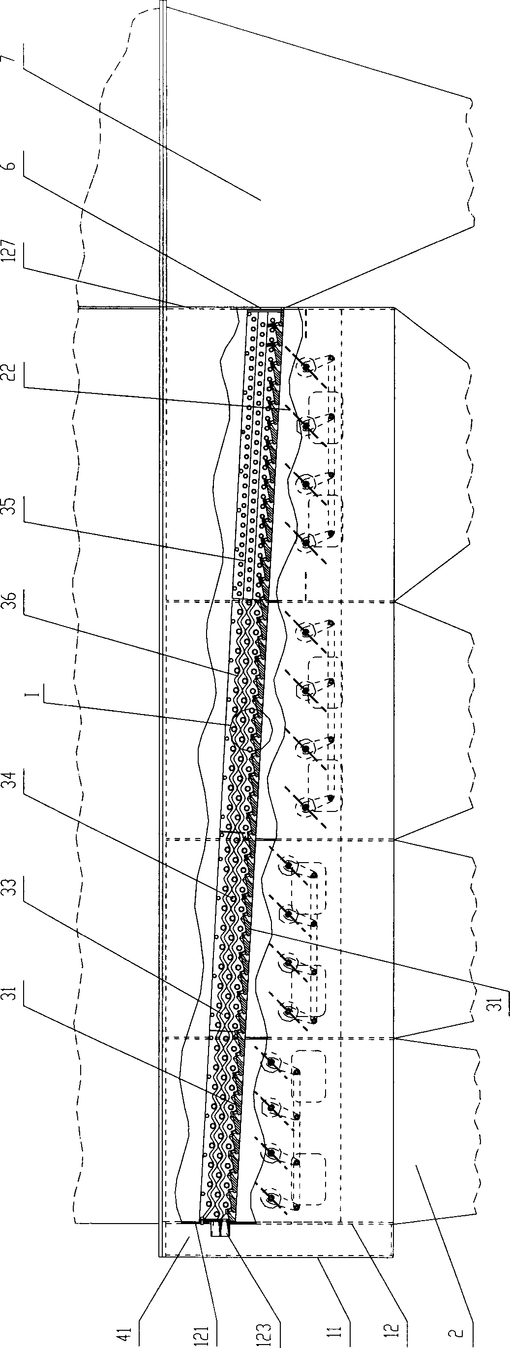
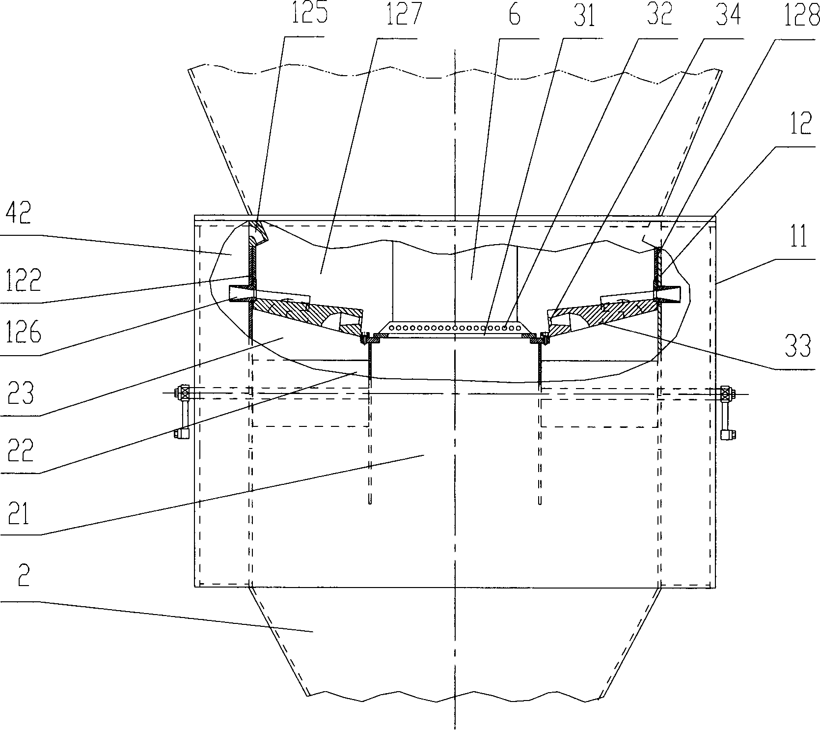
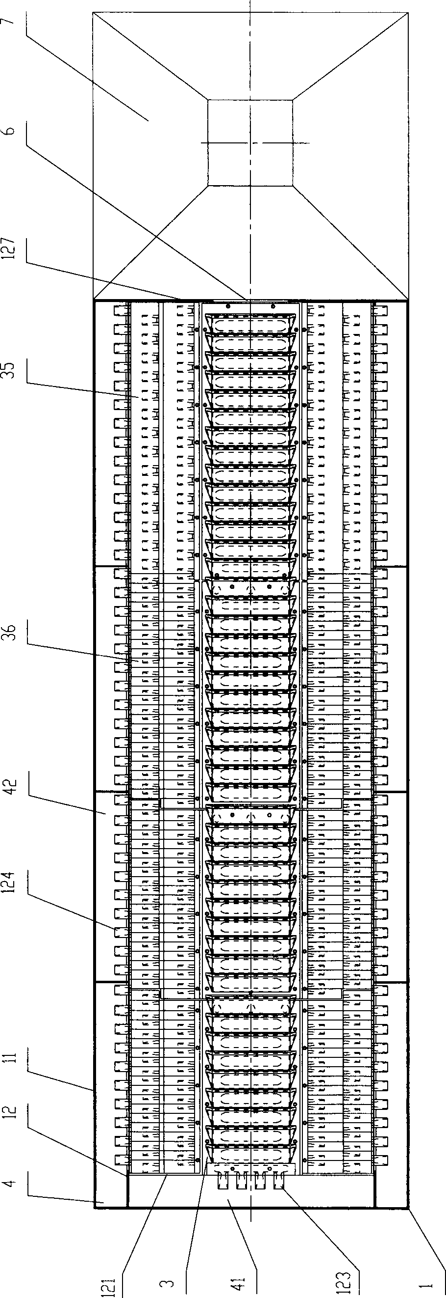
[0025] a kind of like Figure 1 ~ Figure 3 The bed structure of the shown boiling swirling fluidized bed of the present invention includes an outer casing 1 and an air distribution plate 3, and the outer casing 1 and the air distribution plate 3 are covered to form a fluidized bed cavity; the air distribution plate 3 is concave Groove-shaped and inclined from the feed end to the discharge end of the bed, the air distribution plate 3 is mainly composed of the air distribution bottom plate 31 in the middle and the air distribution side plates 33 on both sides. The air distribution bottom plate 31 is provided with boiling swirl The segmented air chamber 2 of the fluidized bed (the segmented air chamber of the boiling swirling fluidized bed generally includes the main air chamber 21, the side air chamber 23, the air volume and pressure regulating door 22 and other components) connected to the air injection bottom hole 32, The air distribution side plate 33 is provided with an air ...
Embodiment 2
[0032] a kind of like Figure 5 ~ Figure 8 The bed structure of the shown boiling swirling fluidized bed of the present invention is basically the same as the fluidized bed structure of embodiment 1, and its difference with embodiment 1 only lies in the following two points: 1) the air distribution side The adjacent upper and lower rows of jet side holes 34 arranged on the plate 33 are all separated by the wave surface 36 on the air distribution side plate 33, and all other components and connection methods are the same as in Embodiment 1; 2) as Figure 8 As shown, in this embodiment, airflow guides (321) are all correspondingly provided on the air distribution bottom plate 31 above each row of air injection bottom holes 32.
Embodiment 3
[0034] a kind of like Figure 9 ~ Figure 12 The bed structure of the shown boiling swirling fluidized bed of the present invention is basically the same as the bed structure of the fluidized bed in Example 1, and the difference with Example 1 is only the following three points: 1) the air distribution side plate 33, the upper and lower rows of air injection side holes 34 are all separated by the flat surface 35 on the air distribution side plate 33; Feed port 6, it is to offer a discharge port 8 connected with the bottom discharge pipe 5 of the fluidized bed at the longitudinal discharge end of the air distribution bottom plate 31, and the fluidized bed of the present embodiment is carried out through the discharge port 8. Discharging; in another specific embodiment, even the rear inner wall discharge opening 6 in embodiment 1 and the discharge opening 8 in the present embodiment can be set at the same time; 3) as Figure 12 As shown, the air distribution bottom plate 31 abov...
PUM
 Abstract
Description
Claims
Application Information
 - R&D
- Intellectual Property
- Life Sciences
- Materials
- Tech Scout
- Unparalleled Data Quality
- Higher Quality Content
- 60% Fewer Hallucinations
Browse by: Latest US Patents, China's latest patents, Technical Efficacy Thesaurus, Application Domain, Technology Topic, Popular Technical Reports.
© 2025 PatSnap. All rights reserved.Legal|Privacy policy|Modern Slavery Act Transparency Statement|Sitemap|About US| Contact US: help@patsnap.com


