Linear ion trap analyzer

An ion trap and analyzer technology, applied in the direction of mass spectrometer, etc., can solve the problems of field adjustment electrode setting and voltage application difficulty, increasing instrument cost, etc.

Active Publication Date: 2011-11-02
SHIMADZU SEISAKUSHO CO LTD
View PDF11 Cites 20 Cited by
  • Summary
  • Abstract
  • Description
  • Claims
  • Application Information

AI Technical Summary

Problems solved by technology

Since there is no position where the AC potential is zero like in the end cap of the 3D ion trap, this makes it difficult to set up the field adjustment electrodes and apply the voltage
[0010] In addition, since ions in the linear ion trap may emerge from the extraction grooves of the two X electrodes after resonance excitation, it is structurally necessary to install ion detectors behind the two X electrodes to receive ion signals to the greatest extent, which increases the cost of the instrument

Method used


Image

  • Linear ion trap analyzer
  • Linear ion trap analyzer
  • Linear ion trap analyzer

Examples


no. 1 example

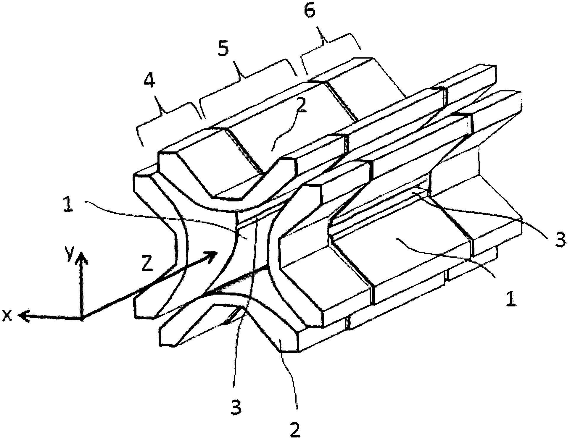
[0037] still refer to figure 1 An example of the present invention will be described. The structure of the two-dimensional linear ion trap is divided into front section 4, middle section 5 and back section 6. The front and back sections 4 and 6 are provided with relatively high potentials to generate axial constraints on ions (for positive ions, it is relatively high for negative ions). low potential, the same hereinafter). Each section has two pairs of main electrodes 1 and 2 in the X and Y directions, on which driving high-frequency voltages in opposite phases are applied to form a radial trapping electric field. In an alternative embodiment, the front section 4 and the rear section 6 can also be replaced by front and rear end cap electrodes, so as to generate a DC or AC trapped electric field in the axial direction. Ions are usually introduced from one end along the Z axis and are trapped in a linear region between two pairs of electrodes along the X and Y axes. If a dip...

no. 2 example

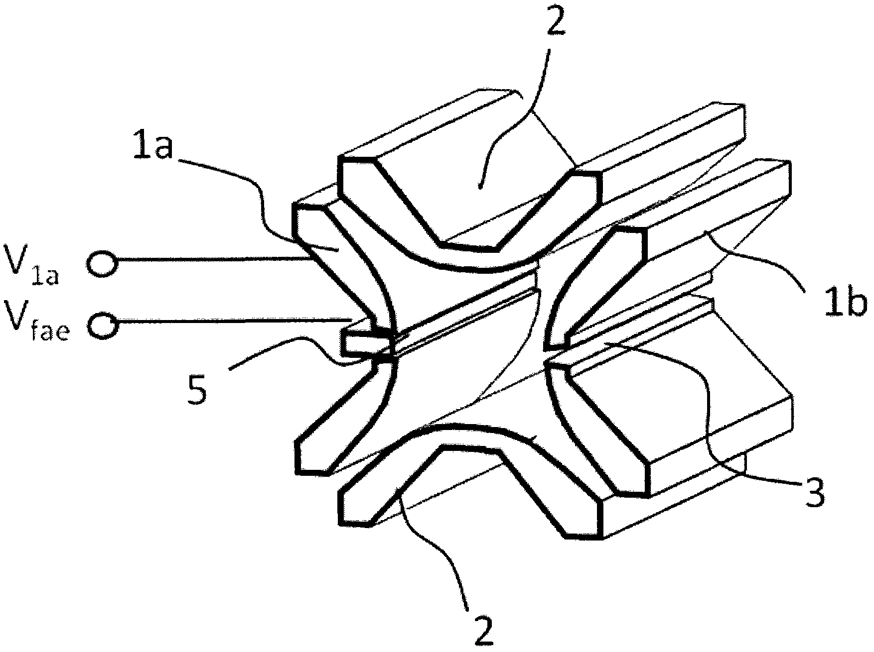
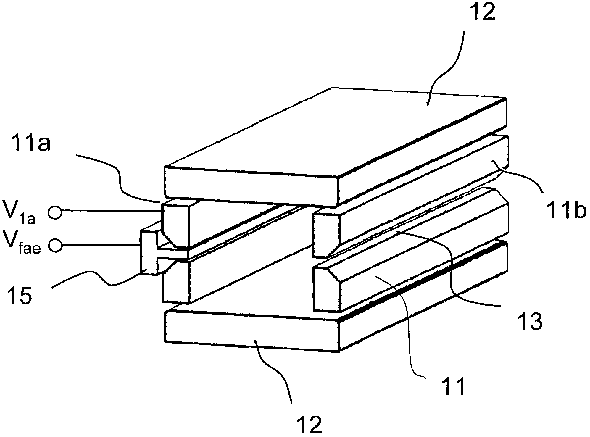
[0044] As mentioned above, planar electrodes, as a special case of cylindrical electrodes, can also be used to form linear ion traps. image 3 A schematic diagram of a rectangular linear ion trap built with four planar electrodes according to the second embodiment of the present invention is given. For clarity and brevity, image 3 Only the middle section is shown, and the front and rear sections or end caps are omitted. refer to image 3 As shown, the two pairs of main electrodes 11 and 12 in the X and Y directions respectively apply driving high-frequency voltages in opposite phases to form a radial trapping electric field. In the middle of the X electrodes 11a opposite to the lead-out slots 13, a field regulating electrode 15 is provided. Similar to the first embodiment, the voltage on the field adjusting electrode is set to be the high-frequency voltage V on the adjacent X electrode 11a 1a at least part of and a DC voltage V DC superposition, that is:

[0045] V fae...

no. 3 example

[0049] In this embodiment, in order to obtain a better quadrupole field shape for the rectangular linear ion trap built with planar electrodes, each electrode plane can be composed of several sub-electrodes, and each sub-electrode is added with a certain proportion of high-frequency Voltage, forming a field shape similar to the electric field generated by a hyperbolic cylinder. The specific details of this type of ion trap can be referred to in Chinese patent CN1585081.

[0050] Figure 4 A cross-sectional structure of a planar printed circuit (PCB) type linear ion trap according to this embodiment is shown. In this embodiment, a planar strip-shaped printed circuit 26 is provided on at least a part of the electrode plates, and a field regulating electrode 25 is provided in the middle of the X electrode plate 21 opposite to the lead-out groove 23 . Wherein, the field adjusting electrode 25 with trapezoidal cross-section can be retracted into the interior of the adjacent X ele...


PUM


Abstract

The invention relates to a linear ion trap analyzer. The linear ion trap analyzer comprises an ion trapping space surrounded by a plurality of cylinder electrodes, wherein high frequency voltage is applied to at least one part of cylinder electrodes so as to generate a radial trapping electric field which mainly has two dimensional quadrupole fields in the trapping space; at least one ion leading-out slot is formed on an ion trap in the direction perpendicular to a center axis, and an alternating electric field for exciting dipoles is overlapped in the direction; a strip-type field regulating electrode is arranged in a slit in the cylinder electrode right opposite to the ion leading-out slot, or in the gap between two cylinder electrodes; and the voltage on the field regulating electrode is set as the sum of all or one part of the high frequency voltage on the adjacent cylinder electrode and direct current (DC) voltage, and the DC voltage can be regulated as required. By setting the field regulating electrode and regulating the DC voltage, one or more aims of optimizing a field form in a linear ion trap and influencing ion motion characteristics during resonance excitation can be fulfilled.

Description

technical field [0001] The invention relates to the technique of using ion traps to perform mass spectrometry analysis on ions, in particular to a linear ion trap analyzer with optimized electric field. Background technique [0002] The traditional quadrupole field ion trap technology has been greatly developed since the 1950s and is widely used in mass spectrometry instruments. Many literatures and patents in this regard are included in the book "Practical Aspects of Ion Trap Mass Spectrometry" written by R.E.March and J.F.J.Todd. The three-dimensional rotating ion trap consists of a ring electrode and a pair of end cap electrodes, forming an analysis space between them, applying a radio frequency voltage on the ring electrode to generate a quadrupole field to trap ions, and applying a dipole alternating voltage between the two end caps Excite ions and selectively discharge ions to achieve the purpose of mass scanning. [0003] Since its commercialization, the two-dimensi...

Claims


Application Information

Patent Timeline
Patent Type & Authority Applications(China)
IPC IPC(8): H01J49/26
Inventor 丁力吝涛蒋公羽穆辉
Owner SHIMADZU SEISAKUSHO CO LTD
Why Eureka
Try Eureka