
Dedusting device

A dust-removing device and accommodating technology are applied in cleaning methods and utensils, chemical instruments and methods, cleaning methods using gas flow, etc., and can solve the problems of destroying the dust-free environment of lenses and affecting the effect of dust removal, etc.

Inactive Publication Date: 2011-11-09
HONG FU JIN PRECISION IND (SHENZHEN) CO LTD +1
View PDF7 Cites 7 Cited by
  • Summary
  • Abstract
  • Description
  • Claims
  • Application Information

AI Technical Summary

Problems solved by technology

However, this method requires manual operation, which will destroy the dust-free environment of the lens
And it is also easy to make the blown dust fall on the lens again, affecting the effect of dust removal

Method used


Image

  • Dedusting device
  • Dedusting device
  • Dedusting device

Examples


Embodiment Construction

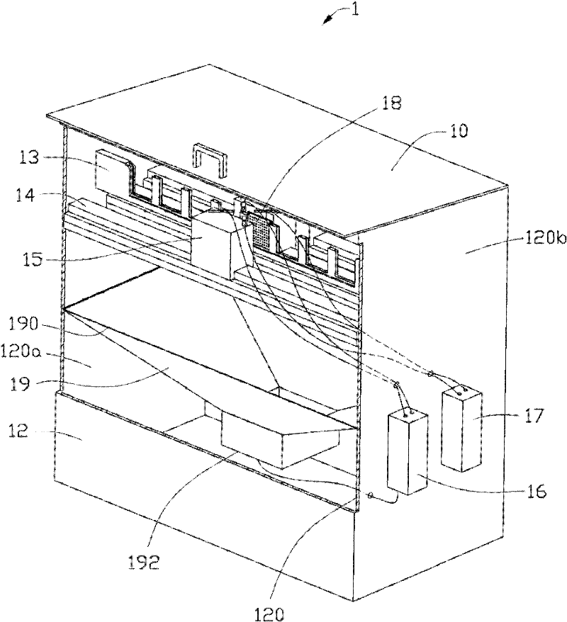
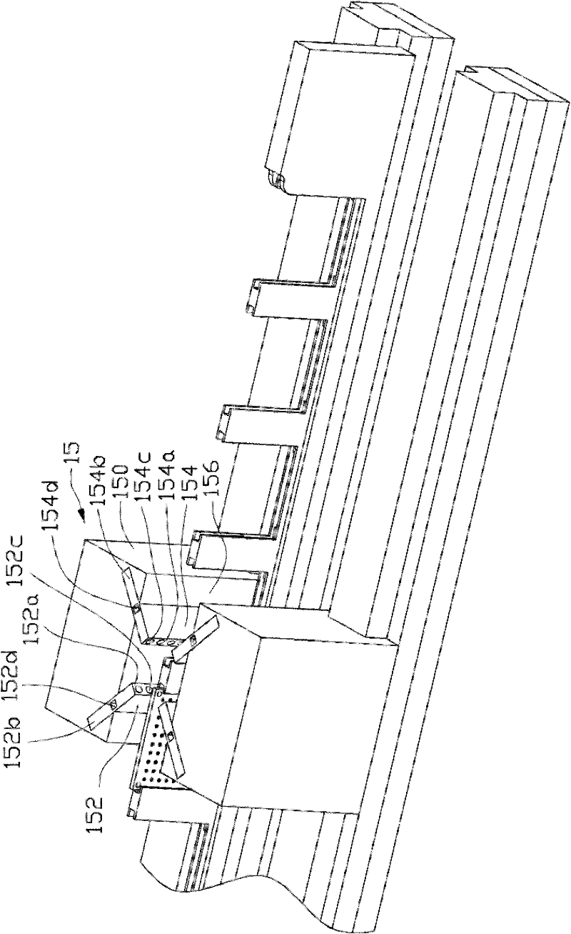
[0042] Such as figure 1 As shown, the dust removal device 1 provided by the embodiment of the present invention includes a top cover 10, an accommodating cavity 12, a bracket 13, a slide rail 14, a dust removal slide 15, an air extractor 16, an air blower 17, and a lens tray 18 and gas collecting hood 19.

[0043] The accommodating cavity 12 is a cuboid cavity with an open upper end. The top cover 10 is used to seal the accommodating cavity 12 to form an airtight accommodating space. The accommodating cavity 12 includes a pair of side walls 120 parallel to each other, and each side wall 120 in the pair of side walls 120 includes an inner surface 120a located inside the accommodating cavity and an inner surface 120a located outside the accommodating cavity 12. The outer surface 120b.

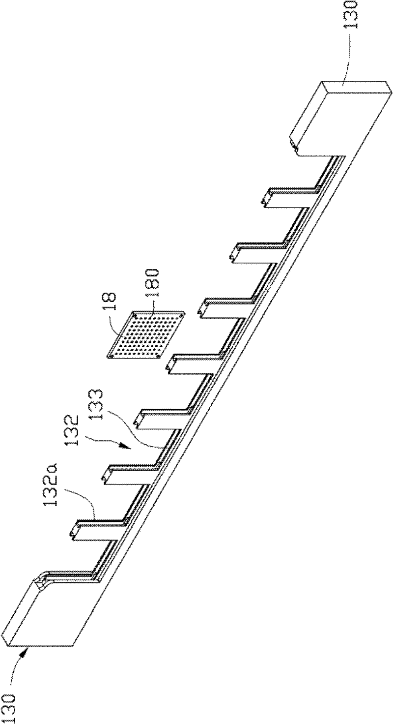
[0044] Please also refer to figure 2 and image 3 , the bracket 13 is an elongated rectangular flat plate, which includes two opposite end surfaces 130 . The middle portion of the bracket ...


PUM


Abstract

The invention provides a dedusting device. The dedusting device comprises a top cover, an accommodation cavity, a bracket, a sliding rail, a dedusting sliding seat, an air extractor, an air blower and a lens bearing disk, wherein the accommodation cavity is provided with an opening; the top cover is used for sealing the opening of the accommodation cavity so as to form a closed accommodation space; two ends of the bracket are respectively fixed in the accommodation cavity; at least one side of the bracket is equipped with the sliding rail parallel to the bracket; the lens bearing disk is fixed on the bracket and used for bearing a lens to be dedusted; the air extractor and the air blower are arranged outside the accommodation cavity; and the dedusting sliding seat is respectively connected with the air extractor and the air blower and slides along the sliding rail so as to blow and suck air for the lens bearing disk fixed on the bracket at the same time, thereby blowing off and sucking out ash on the lens.

Description

technical field [0001] The invention relates to a dust removal device, in particular to a dust removal device for removing dust on a lens. Background technique [0002] Before the lens is coated, it is usually necessary to remove the dust on the lens surface to ensure the cleanliness of the lens surface and improve the coating quality. At present, the way to remove dust on the lens is generally to place the lens on a carrier plate, then pick up the carrier plate with one hand, and hold the ion air gun to blow dust on the lens with the other hand. However, this method requires manual operation, which will destroy the dust-free environment of the lens. And it is also easy to make the blown dust fall on the lens again, affecting the effect of dust removal. Contents of the invention [0003] In view of this, it is necessary to provide a dust removal device that can effectively remove dust on the lens. [0004] A dust removal device comprises a top cover, an accommodating ca...

Claims


Application Information

Patent Timeline
IPC IPC(8): B08B5/00
Inventor 郭明龙
Owner HONG FU JIN PRECISION IND (SHENZHEN) CO LTD
Learn More