Spiral toilet blow-off pipe

A sewage pipe and spiral technology, which is applied in the field of sanitary ware, can solve the problems that the diameter of the pipe cannot be made too thick, the straight part of the S pipe is short, and the negative pressure is small.

Inactive Publication Date: 2011-11-09
华彬
View PDF3 Cites 3 Cited by
  • Summary
  • Abstract
  • Description
  • Claims
  • Application Information

AI Technical Summary

Problems solved by technology

[0008] In addition, the current S tube used as water storage and replacement has a great defect in function: due to the limitation of the height of the toilet base, the straight part of the S tube is very short, and the negative pressure formed in t...

Method used


Image

  • Spiral toilet blow-off pipe
  • Spiral toilet blow-off pipe

Examples


Embodiment Construction

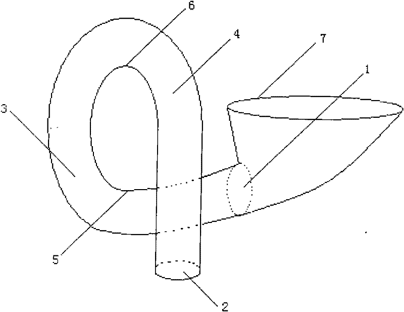
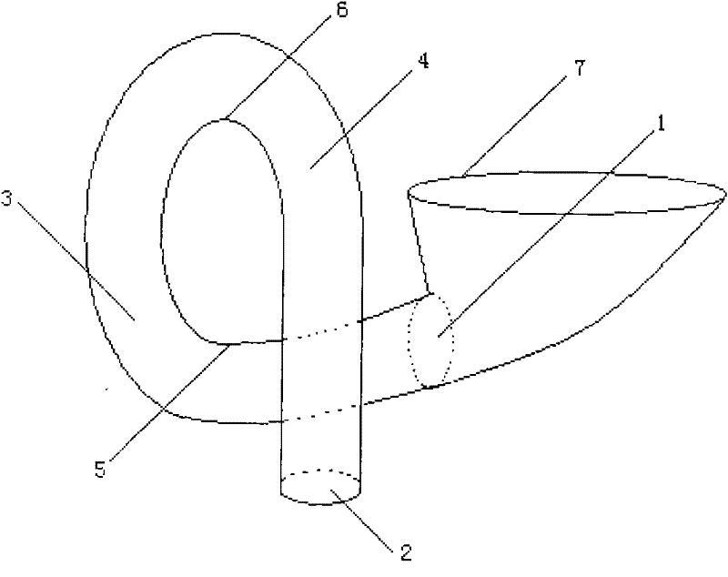
[0022] figure 1 The specific implementation manner of the spiral toilet sewage pipe of the present invention is shown. The entrance section 1, the top-spin section 3, the down-spin section 4, and the outlet section 2 form a staggered approximate spiral ring. As long as the pipe wall is smooth and the inner wall of the pipe is smooth, the thickness and shape of the pipe can be adjusted arbitrarily. After washing the bedpan 7 with water with a certain level of potential energy, the inertia of the water flow forms a vortex in the interval between the inlet section 1 and the upturn section 3. Because of the extrusion of the subsequent water flow, the dirt in the bedpan rolls down with the vortex flow. The bottom wall 6 at the highest point of the rotary section is discharged from the outlet section 2 smoothly. The end position of the outlet section 2 can be adjusted arbitrarily according to the position of the water outlet distance of the building. The depth of toilet water seal...


PUM


Abstract

The invention discloses a spiral toilet blow-off pipe. The spiral toilet blow-off pipe comprises an inlet section, an outlet section, an upper spiral section, a lower spiral section, a lowest top wall of the upper spiral section and a highest top wall of the lower spiral section. The inlet section, the outlet section, the upper spiral section and the lower spiral section are designed into an approximately spiral hollow ring; the upper spiral section and the lower spiral section are not in the same plane; and after eddy current is formed through the inlet section and the upper spiral section by using the inertia force of the water flow, the direction of the eddy current is basically consistent with the structure of the pipe, and the force attenuation of the water flow is extremely low, so that dirt can flow out of the lower spiral section very smoothly. In the whole displacement process, the siphon condition is made without a higher water head at the inlet or jet water flow of higher pressure, so that the spiral toilet blow-off pipe has four advantages of water saving, forcible scouring, difficulty in blockage due to large caliber and complement displacement compared with an S-shaped low-off pipe.

Description

Technical field: [0001] The invention relates to a sanitary appliance, in particular to a spiral type toilet sewage discharge pipe which can not only ensure a certain water sealing depth and a super large diameter, but also keep the inertial force of the water flow as much as possible and reduce the sewage discharge resistance. Background technique [0002] Sanitary ware has a history of more than 500 years. It is reasonable to say that the structure should be finalized. It has gone through a long process of exploration during the evolution from the relatively water-consuming in the past to the comparatively water-saving today. [0003] Sanitary ware looks simple, but in fact it is a comprehensive application of very complex fluid mechanics knowledge. A slight change in the flushing structure will directly affect the effect of washing and replacement. In today's era when the world is short of water resources and the world is advocating energy conservation and emission reduc...

Claims


Application Information

Patent Timeline
IPC IPC(8): E03D11/18
Inventor 华彬
Owner 华彬
Why Eureka
Try Eureka