Pedal type linkage siphon pedestal pan
A toilet and foot-operated technology, applied in the field of foot-operated linkage siphon toilets, can solve problems such as inability to achieve water-saving effects
- Summary
- Abstract
- Description
- Claims
- Application Information
AI Technical Summary
Problems solved by technology
Method used
Image
Examples
Embodiment 1
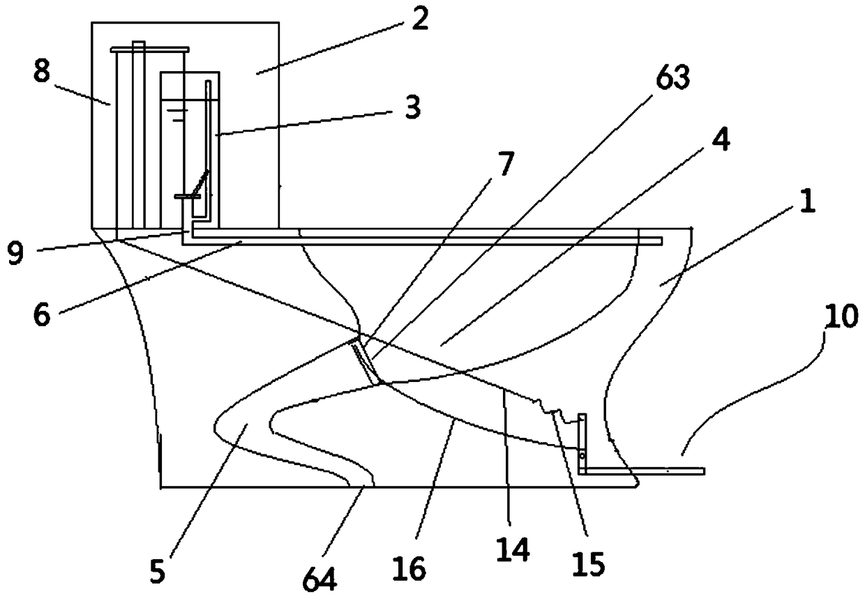
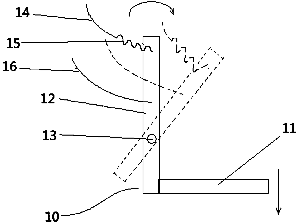
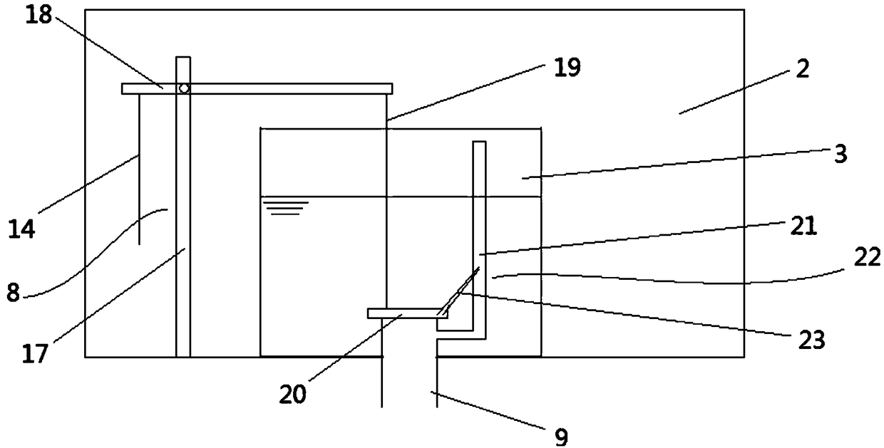
[0037] A foot-operated linkage siphon toilet, its structure is as follows Figure 1~3 , Figure 9-10 As shown, including the toilet body 1, the water tank, and the siphon pipeline 5, the inside of the toilet body 1 is provided with a submerged bay 4, and the water inlet of the submerged bay 4 is connected with the water tank through the flushing pipeline 6, and the water outlet 63 of the submerged bay is connected with the water tank. The siphon pipeline 5 is connected, and the siphon pipeline water outlet 64 is connected with the sewer pipe. The water tank includes an outer water tank 2 and an inner water tank 3 arranged inside the outer water tank 2. The valve outlet a9 passes through the bottom of the inner water tank 3 and the outer water tank 2 and is sealed and fixedly connected with the inner water tank 3 and the outer water tank 2. The outer water tank 2 is provided with a drain valve unit 8 for opening the drain valve a20 and a drain valve unit 8 for opening the water...
Embodiment 2
[0044] Using the same inner water tank 3, outer water tank 2, toilet body 1, water inlet unit, siphon pipeline 5 as in the embodiment, the difference is that a different drain valve unit 8 is used, specifically as Figure 4-8 shown.
[0045] The water discharge valve unit 8 includes a rotatable rotating water discharge frame 24 arranged in the outer water tank 2, a water discharge switch and a water discharge valve mechanism b30 connected with the water discharge switch. 25. The water-discharging frame linkage bar b29 on the top, the water-discharging switch comprises two buttons 35 arranged side by side at the same height, a depression bar 36 and a lever 37 arranged at the bottom of each button 35, and the depression bar 36 length under the two buttons 35 is different. same as Figure 7 As shown, the fulcrum of the lever 37 is located in the middle of the lever 37, one end of the lever 37 is located below the two pressure rods 36, the other end of the lever 37 is connected w...
PUM
 Abstract
Description
Claims
Application Information
 - R&D
- Intellectual Property
- Life Sciences
- Materials
- Tech Scout
- Unparalleled Data Quality
- Higher Quality Content
- 60% Fewer Hallucinations
Browse by: Latest US Patents, China's latest patents, Technical Efficacy Thesaurus, Application Domain, Technology Topic, Popular Technical Reports.
© 2025 PatSnap. All rights reserved.Legal|Privacy policy|Modern Slavery Act Transparency Statement|Sitemap|About US| Contact US: help@patsnap.com


