
Gas valve

A technology for air valves and valve seats, which is applied in the field of dry-running air valves, and can solve problems such as temperature rise of valve components

Active Publication Date: 2011-11-09
HOERBIGER KOMPRESSORTECHNIK HLDG GMBH
View PDF9 Cites 3 Cited by
  • Summary
  • Abstract
  • Description
  • Claims
  • Application Information

AI Technical Summary

Problems solved by technology

However, in dry-running compressor valves, ie without such inherent lubrication, the valve element cannot be guided centrally on the intermediate pin due to friction and the associated wear and temperature rise.

Method used


Image

  • Gas valve
  • Gas valve

Examples


Embodiment Construction

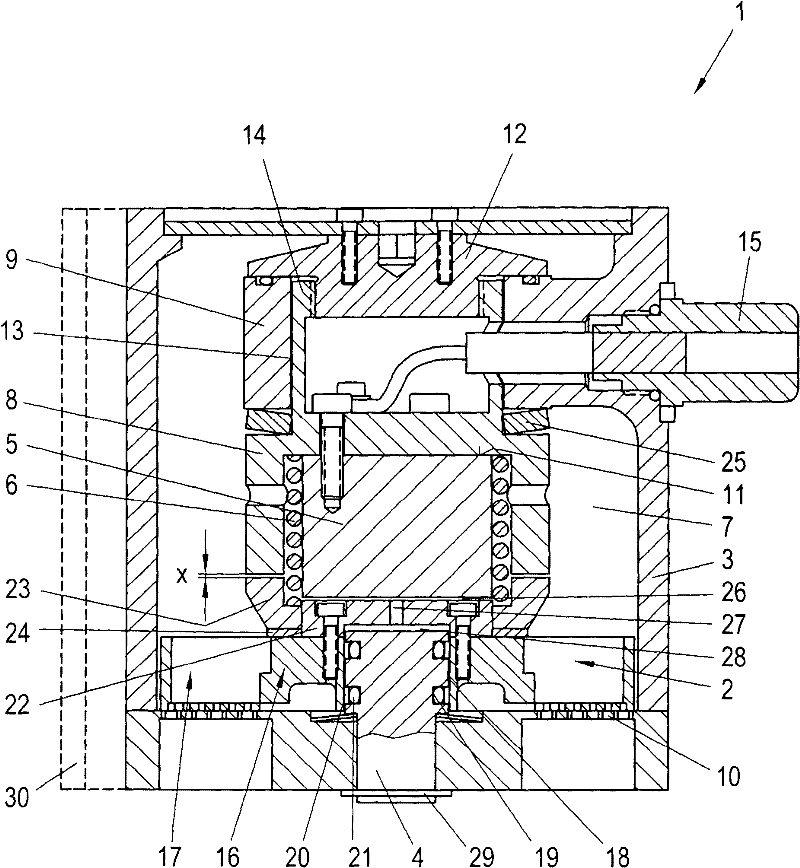
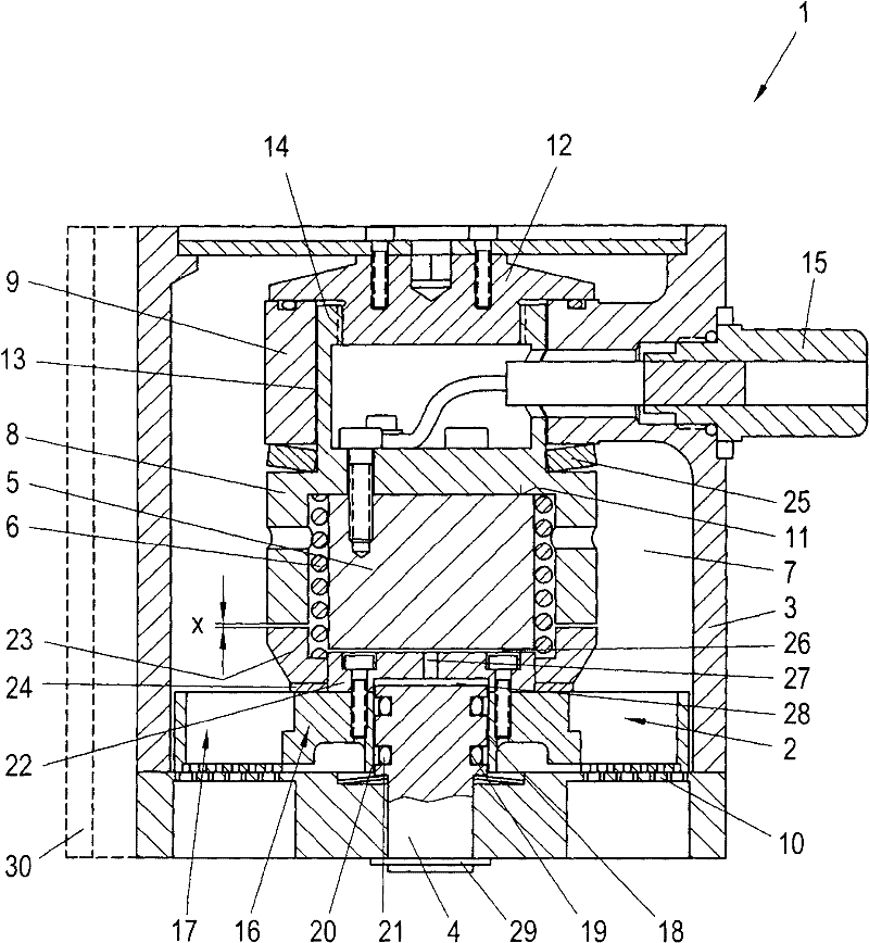
[0018] as in figure 1 As shown in , the gas valve 1 according to the invention comprises a housing 3 in which an intermediate part 9 is arranged. At one axial end of the gas valve 1 there is a valve seat 10 which thus simultaneously forms the gas outlet of the gas valve 1 . The valve seat can be part of the housing 3 . Here, a gas inlet is provided at the opposite axial end of the gas valve 1 . The gas valve 1 shown here is therefore axially flowed through. However, it is of course equally possible that the gas can also be supplied radially at suitable points in the housing 3 .

[0019] An adjusting element 8 is arranged in the intermediate part 9 . The adjusting part 8 is here guided and supported in a recess 13 of the intermediate part 9 and is held by the thread 14 of the adjusting nut 12 at the axial end facing away from the valve seat 10 . The adjusting nut 12 bears axially against the axial end of the intermediate part 9 here. The adjusting element 8 can thus be mo...


PUM


Abstract

The present invention relates to a dry running gas valve. In order to achieve high opening speeds in a dry running gas valve with electromagnetic actuation, it is provided to arrange the engagement point of the magnet armature (22) and the limit stop at the radially inner guide region (16) of the valve element (2). Due to the resulting reduced deflection, the valve element can be built more compact and lighter and the residual air gap can be reduced, which allows higher opening speeds.

Description

technical field [0001] The invention relates to a dry-running gas valve comprising a disc-shaped valve element with a plurality of through-flow channels, which cooperates in a sealing manner with a valve seat, wherein the valve element is connected to an armature which is arranged in a gas The electromagnets in the valve act in concert. Background technique [0002] Gas valves for supplying gaseous fuel into the combustion chamber of an internal combustion engine require a large opening cross-sectional area in order to be able to introduce sufficient gaseous fuel into the cylinder chamber within the short available opening times. Such gas valves are usually opened by means of electromagnets, wherein the electromagnets must be able to achieve a sufficient stroke and must exert sufficient magnetic force in order to be able to supply the required gas volume within a short opening time. Furthermore, opening and closing times as short as possible are desirable, so that the time ...

Claims


Application Information

Patent Timeline
Patent Type & Authority Applications(China)
IPC IPC(8): F02M21/02F02M51/06
CPCY02T10/32F02M21/0272F02M21/0254F02M21/0251F02M51/06Y02T10/30Y10T137/86759Y10T137/87426
Inventor G·兰尼格M·格
Owner HOERBIGER KOMPRESSORTECHNIK HLDG GMBH
Learn More