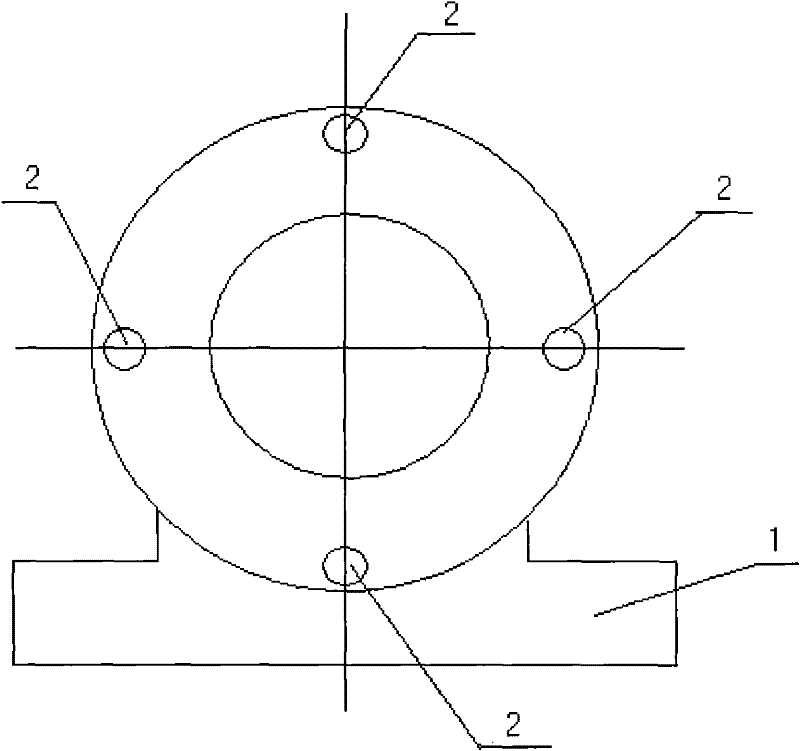
Structure of bearing pedestal of three-roller bending machine
A technology of bearing seat and trigger, which is applied to the rigid support of bearing components, bearing elements, shafts and bearings, etc., which can solve the problems of good heat dissipation, easy temperature damage of bearing seats and bearings, etc., and achieve good heat dissipation and easy improvement Damage, the effect of improving the service life
Inactive Publication Date: 2011-11-09
张桂华
View PDF0 Cites 2 Cited by
- Summary
- Abstract
- Description
- Claims
- Application Information
AI Technical Summary
Problems solved by technology
[0004] The technical solution adopted by the present invention to solve the technical problem is: the structure is composed of a bearing seat and a heat dissipation hole. Since a plurality of through heat dissipation holes are arranged on the bearing seat, it has good heat dissipation, so it can effectively Greatly improve the problem that the bearing seat and the bearing are easily damaged due to the high temperature of the friction force in the current machining
Method used
View moreImage
Smart ImageViewing Examples
Examples
Embodiment Construction
[0009] The structure is composed of a bearing seat (1) and a cooling hole (2). Since the bearing seat (1) is provided with a plurality of through cooling holes (2), it has good heat dissipation, so it can improve the friction due to friction. The effect is that the temperature of the bearing seat and the bearing is too high and it is easy to be damaged.
Login to View More PUM
 Abstract
A structure of a bearing pedestal of a three-roller bending machine comprises a bearing pedestal and heat-dissipating holes; a plurality of heat-dissipating through holes are disposed on the bearing pedestal, and the bearing pedestal has good heat dissipation, so the problem of easy damage of the bearing pedestal and the bearing due to excessive high temperature caused by friction is solved; the invention has good heat dissipation, can solve the problem of easy damage of the bearing pedestal and the bearing caused by large friction and high temperature, can increase the service life of the bearing pedestal and the bearing, and thus has good application effect.
Description
technical field [0001] The invention relates to a bearing seat of a three-roller plate bending machine, in particular to a structure of a bearing seat of a three-roller plate bending machine, and belongs to the technical field of machinery. Background technique [0002] So far, the types of bearing housings include split bearing housings, bearing housings with flanges, outer spherical bearing housings, etc., bearing housings are a structure for placing fixed bearings on machinery; at present, the working rolls of three-roll plate rolling machines use During the working process of the rolling bearing seat, due to the action of friction, the temperature of the bearing seat and the bearing is too high, which is prone to damage, which is easy to cause passive work. Contents of the invention [0003] The purpose of the present invention is to provide a structure for the bearing seat of a three-roller plate bending machine, which can improve the problem that the current bearing ...
Claims
Login to View More Application Information
Patent Timeline
 Patent Type & Authority Applications(China)
IPC IPC(8): F16C35/06B21D5/14
Inventor 张桂华
Owner 张桂华
Features
- R&D
- Intellectual Property
- Life Sciences
- Materials
- Tech Scout
- Unparalleled Data Quality
- Higher Quality Content
- 60% Fewer Hallucinations
Learn More Browse by: Latest US Patents, China's latest patents, Technical Efficacy Thesaurus, Application Domain, Technology Topic, Popular Technical Reports.
© 2025 PatSnap. All rights reserved.Legal|Privacy policy|Modern Slavery Act Transparency Statement|Sitemap|About US| Contact US: help@patsnap.com

