Sound sensor with electromagnetic wave receiver

A sound sensor, electromagnetic wave technology, applied in the direction of sensors, electrical components, transducer circuits, etc., can solve the problem of short circuit of sound sensors, and achieve the effect of reducing the size, reducing the packaging difficulty, and improving the packaging yield.

Inactive Publication Date: 2011-11-09
ALCOR MICRO CORP
View PDF5 Cites 3 Cited by
  • Summary
  • Abstract
  • Description
  • Claims
  • Application Information

AI Technical Summary

Problems solved by technology

[0009] Another object of the present invention is to overcome the defects of the existing sound sensor, and provide a sound sensor with a novel structure with an electromagnetic wave receiver. The technical problem to be solved is to make it use an insulating upper cover and a Non-conductive adhesive to avoid the short circuit of the sound sensor during packaging, thereby improving the packaging yield of the sound sensor and reducing the difficulty of packaging

Method used


Image

  • Sound sensor with electromagnetic wave receiver
  • Sound sensor with electromagnetic wave receiver
  • Sound sensor with electromagnetic wave receiver

Examples


Embodiment Construction

[0043] In order to further illustrate the technical means and effects that the present invention adopts to achieve the intended purpose of the invention, below in conjunction with the accompanying drawings and preferred embodiments, the specific implementation, structure, Features and their functions are described in detail below.

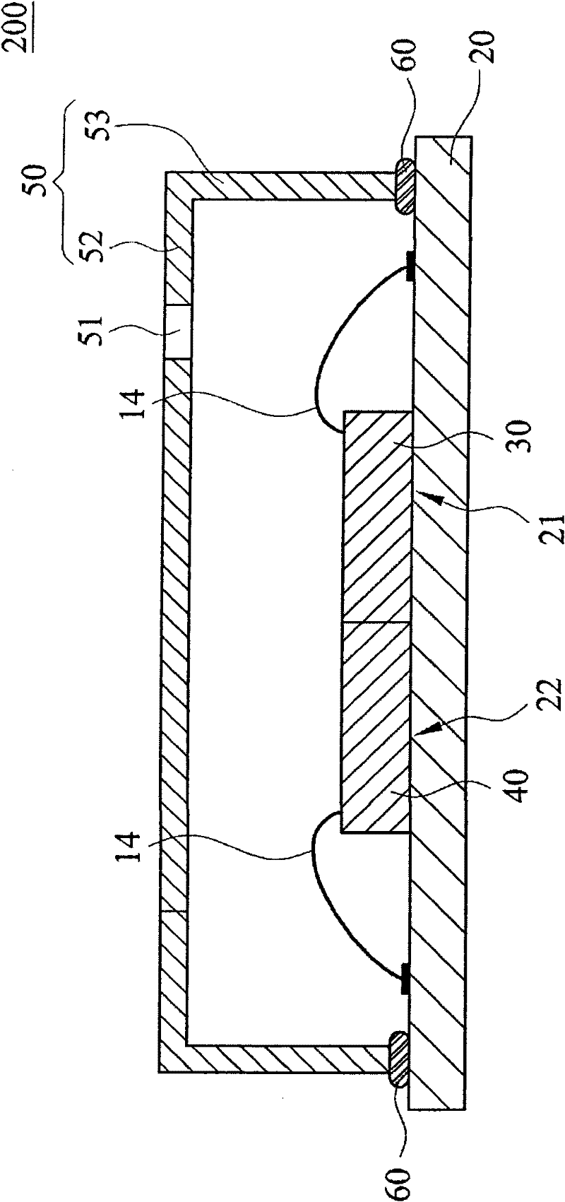
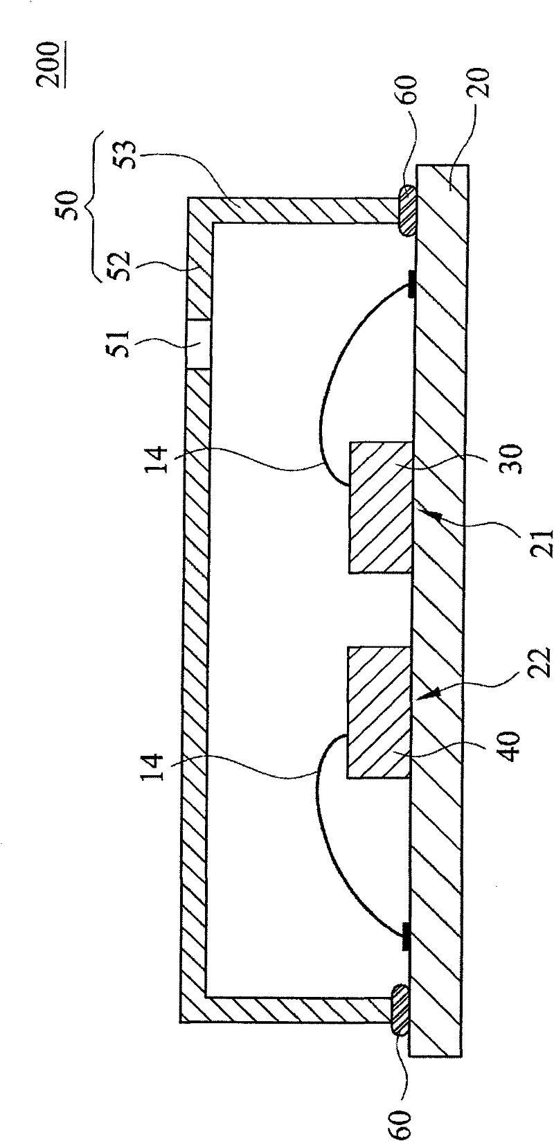
[0044] Figure 2A It is a cross-sectional embodiment diagram of an acoustic sensor 200 with an electromagnetic wave receiver 40 of the present invention. Figure 2B It is a cross-sectional embodiment diagram of another acoustic sensor 200 with an electromagnetic wave receiver 40 of the present invention. image 3 for Figure 2A The top view example diagram. Figure 4AIt is a schematic cross-sectional view of a MEMS microphone 30 of the present invention. Figure 4B It is a schematic cross-sectional view of an electromagnetic wave receiver 40 of the present invention. Figure 5 It is a cross-sectional embodiment diagram of an acoustic sensor 20...


PUM


Abstract

The invention relates to a sound sensor with an electromagnetic wave receiver. The sound sensor comprises a circuit substrate, a micro electromechanical system microphone, the electromagnetic wave receiver and an upper insulating cover. The micro electromechanical system microphone and the microelectronic wave receiver are arranged on the circuit substrate respectively. The upper insulating cover is arranged on the circuit substrate, and covers the micro electromechanical system microphone and the electromagnetic wave receiver. The micro electromechanical system microphone receives sound signals and electromagnetic wave signals, and the sound signals are mixed with the electromagnetic wave signals to form mixed signals. The electromagnetic wave receiver has a structure similar to that of the micro electromechanical system microphone, but only receives the electromagnetic wave signals and generates electromagnetic wave noise signals. Therefore, recovered sound signals similar to the originally received sound signals can be generated by operating the mixed signals and the electromagnetic wave noise signals to reduce the interference of the electromagnetic wave noise signals.

Description

technical field [0001] The invention relates to an acoustic sensor with an electromagnetic wave receiver, in particular to an acoustic sensor with an electromagnetic wave receiver applied to a micro-electromechanical acoustic sensor. Background technique [0002] figure 1 It is a known package structure of the sound sensor 10 . Such as figure 1 As shown, the packaging structure of the acoustic sensor 10 includes a substrate 11 , a transducer 12 and an upper cover 13 . [0003] Wherein, the substrate 11 has a first surface 111, and a circuit structure is arranged on the substrate 11, which can be used in subsequent manufacturing processes. The transducer 12 is disposed on the first surface 111 of the substrate 11 , and the transducer 12 is electrically connected to the circuit structure on the substrate 11 by using the metal wire 14 by wire bonding technology. The upper cover 13 covers the first surface 111 of the substrate 11 , and forms an airtight accommodating space w...

Claims


Application Information

Patent Timeline
Patent Type & Authority Applications(China)
IPC IPC(8): H04R3/00
Inventor 张琦栋林毅杰
Owner ALCOR MICRO CORP
Why Eureka
Try Eureka