
Automatic measurement range switching device of electronic current transformer

A current transformer and automatic range technology, applied in the direction of inductors, circuits, transformers, etc., can solve the problems of power station protection system misjudgment, protection system misjudgment, protection signal buried, etc., to achieve high precision and large range measurement, Get rid of background electromagnetic interference and enhance the effect of anti-interference ability

Inactive Publication Date: 2011-06-29
西安华伟光电技术有限公司
View PDF0 Cites 34 Cited by
  • Summary
  • Abstract
  • Description
  • Claims
  • Application Information

AI Technical Summary

Problems solved by technology

The existing problem is: when the analog input range of the A / D conversion chip includes a large protection measurement range, when it operates within the rated range, the protection output voltage of the current sensor is only tens of millivolts. Space electromagnetic interference is usually on the order of 20-50mV, so the protection signal will be buried in the electromagnetic noise, which can easily cause misjudgment and malfunction of the power station protection system
Since all kinds of electronic current transformers recently developed in China implement the industrial standard of "IEC60044-8-2002" or "GB / T20840.8-2006", in order to ensure that the device has a large enough protection range, its The protection signal of the rated measurement range can only be set in the order of several millivolts. Therefore, the above-mentioned current transformer products generally have shortcomings such as large interference when the signal is small, and easy misjudgment and misoperation of the protection system in practical applications.

Method used


Image

  • Automatic measurement range switching device of electronic current transformer
  • Automatic measurement range switching device of electronic current transformer
  • Automatic measurement range switching device of electronic current transformer

Examples


Embodiment Construction

[0011] The content of the present invention will be further described below in conjunction with the drawings, but the actual production structure of the present invention is not limited to the following embodiments.

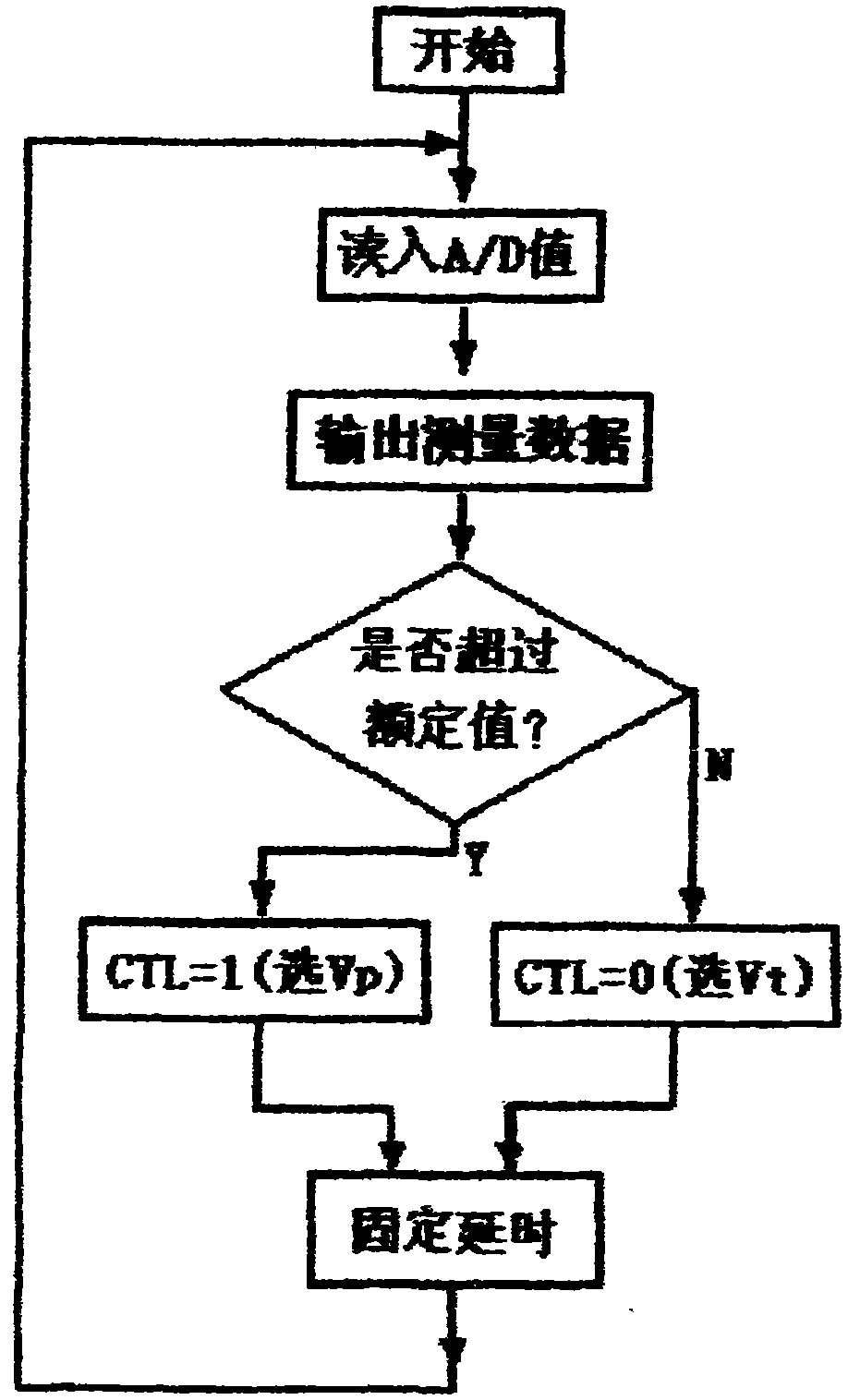
[0012] See attached figure 1 , The electronic current transformer automatic range switching device of the present invention consists of a current sensor (CT) 1, a "choose one" electronic switch (SW) 2, an A / D converter 3 and a microprocessor (MCU) 4 composition. The current sensor 1 is provided with two variable ratio output terminals Vt and Vp, where the Vt terminal is the rated output and the Vp terminal is the protection output, and Vt=kVp (k is a positive integer of 5-50). The two variable ratio output terminals Vt and Vp are respectively connected to one input terminal of the electronic switch 2, and the output terminal of the electronic switch 2 is connected to the input terminal Vin of the A / D converter 3, which is converted by the A / D converter 3. After it ...


PUM


Abstract

The invention relates to an automatic measurement range switching device of an electronic current transformer, which comprises a current sensor, a single-pole two-throw electronic changeover switch, an A / D converter and a microprocessor. The two outputs with different transformation ratios of the current sensor are both connected with one input end of the electronic changeover switch, the output of the electronic changeover switch is converted to digital quantity through the A / D converter and then read-in by the input end of the microprocessor, and the measurement range control output end of the microprocessor is connected with the changeover control end of the electronic changeover switch. The automatic measurement range switching device provided by the invention can conduct automatic switchover according to the signal variation amplitude; and in case of low current, the A / D converter adopts large measurement input to increase signal-to-noise ratio, and in case of heavy current, the switch is switched to protecting signal input to ensure large A / D input range. Through the use of the automatic measurement range switching device, the electronic current transformer can use the same A / D channel to realize high precision and large-range measurement at the same time, so as to enhance the antijamming capability of small signals.

Description

Technical field [0001] The invention belongs to the technical field of power measurement and relay protection devices, and relates to a digital measurement protection device suitable for modern electronic current transformers. Background technique [0002] In addition to the measurement application that must meet the rated range, the electronic current transformer must also meet the application of a larger protection range. The protection range is often 5 to 50 times the rated measurement range. The new generation of electronic current transformers uses digital output. Since the analog input range of the A / D conversion chip is small, generally within 2.5Vpp, the secondary output of the current sensor must be limited to within 2.5Vpp. The problem is: when the analog input range of the A / D conversion chip includes a larger protection measurement range, the protection output voltage of the current sensor is only tens of millivolts when operating within the rated range. Space electr...

Claims


Application Information

Patent Timeline
IPC IPC(8): H01F38/28H01F38/32G01R19/25
Inventor 刘忠战仵勋
Owner 西安华伟光电技术有限公司
Learn More