Phase noise measurement method and device based on radio frequency cancellation

A phase noise and measurement method technology, applied in the direction of noise figure or signal-to-noise ratio measurement, can solve the problems of increasing measurement complexity, reducing measurement accuracy, increasing calibration complexity, etc., achieving strong adjustability, suppressing carrier, The effect of avoiding electromagnetic interference

Inactive Publication Date: 2017-01-18
NANJING UNIV OF AERONAUTICS & ASTRONAUTICS
View PDF7 Cites 33 Cited by
  • Summary
  • Abstract
  • Description
  • Claims
  • Application Information

AI Technical Summary

Problems solved by technology

The phase-locked loop is to keep the signals of the two input phase detectors orthogonal to each other. In order to ensure the orthogonality of the two channels, the phase-locked loop is required to have a certain bandwidth, so that the phase noise lower than the bandwidth of the phase-locked loop will be eliminated. Phase-locked loop suppression requires reverse correction of the measured value, which complicates the measurement process and reduces the measurement accuracy; the phase detector is to convert the phase difference of the two input signals into a voltage, and the phase detector's The output is not only related to the phase difference of the two input signals, but also related to their amplitude, and the influence of the entire measurement system on the signal amplitude is unpredictable, so the system needs to be calibrated before measurement, and the calibration result is consistent with the source under test. Amplitude dependent, further increasing the complexity of the calibration
To sum up, in the delay line frequency discrimination technology and phase detection technology, it is necessary to calibrate the system to correct the influence of the phase-locked loop and phase detector on the measurement results, and the calibration process is related to the input signal amplitude, which increases the Measurement complexity reduces measurement accuracy

Method used


Image

  • Phase noise measurement method and device based on radio frequency cancellation
  • Phase noise measurement method and device based on radio frequency cancellation
  • Phase noise measurement method and device based on radio frequency cancellation

Examples


Embodiment Construction

[0021] The technical scheme of the present invention is described in detail below in conjunction with accompanying drawing:

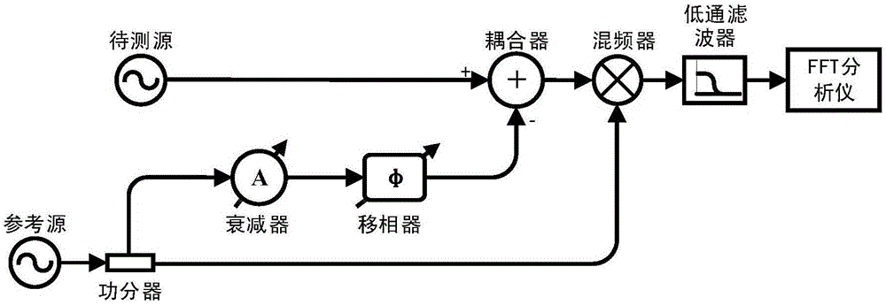
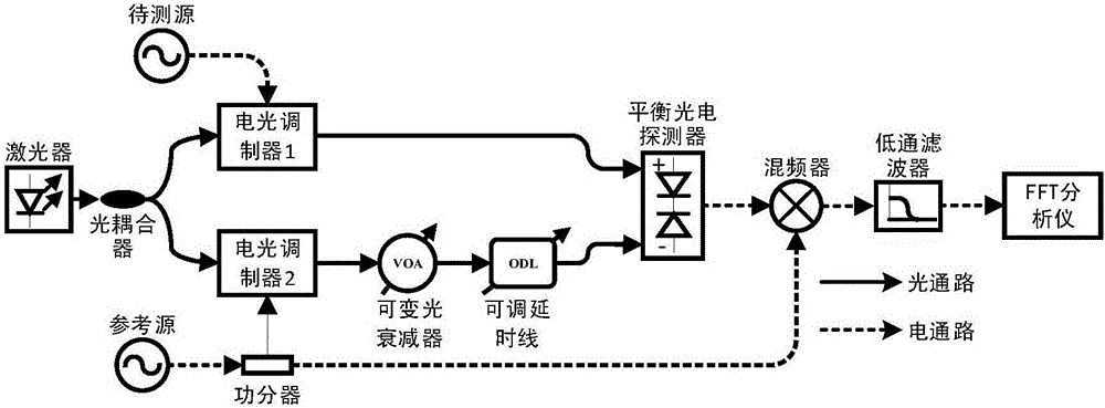
[0022] The purpose of the present invention is: to overcome the deficiencies such as inaccurate measurement and complicated calibration process caused by phase-locked loops and phase detectors in the existing phase noise measurement technology; The phase modulation of the carrier is converted into the amplitude modulation of suppressing the carrier, suppressing the carrier and improving the measurement sensitivity, so that the phase detector and the phase-locked loop can be removed, the calibration process is simplified, and the measurement accuracy is improved.

[0023] The phase noise measurement device based on radio frequency cancellation of the present invention includes a reference microwave source, a power divider, a radio frequency cancellation unit, a mixer, a low-pass filter, and a spectrum analysis unit; A reference microwave signal with the ...


PUM


Abstract

The invention discloses a phase noise measurement method based on radio frequency cancellation. The method comprises the following steps: dividing reference microwave signals at the same frequency as to-be-measured microwave signals into two channels; using one channel of reference microwave signals to cancel the to-be-measured microwave signals so as to convert carrier phase modulation by phase noise into suppression of carrier amplitude modulation; then, performing coherent demodulation on the canceled signals and the other channel of reference microwave signals; and finally, making a spectrum analysis of the low-frequency component of the signals after coherent demodulation to get the phase noise of the to-be-measured microwave signals. The invention further discloses a phase noise measurement device based on radio frequency cancellation. Compared with the prior art, the measurement sensitivity is higher, and the calibration process is easier.

Description

technical field [0001] The invention relates to a phase noise measurement method and device. Background technique [0002] Phase noise is an important index to evaluate the short-term frequency stability of microwave sources. Many of today's microwave and RF systems place increasing demands on the phase noise of microwave sources, such as wireless communication systems, radar systems, and digital-to-analog conversion (ADC) systems. In a wireless communication system, the phase noise of the microwave source in the transmitter affects the modulation of the uplink, and the phase noise of the microwave source in the receiver affects the demodulation of the downlink, which eventually leads to a decrease in the signal-to-noise ratio of the demodulated signal. The bit error rate increases; in radar systems, the phase noise of the local oscillator limits the range resolution and receiver sensitivity of the radar. In particular, in order to accurately detect the target in the Doppl...

Claims


Application Information

Patent Timeline
Patent Type & Authority Applications(China)
IPC IPC(8): G01R29/26
CPCG01R29/26
Inventor 张方正史经展潘时龙
Owner NANJING UNIV OF AERONAUTICS & ASTRONAUTICS
Why Eureka
Try Eureka