Injection device with holding means to prevent unintentional movements of piston rod

A technology for injection devices and holding devices, which is applied in the direction of syringes, ampoule syringes, hypodermic injection devices, etc., can solve the problems of difficult to achieve precise manufacturing and high cost, and achieve the effect of convenient display

Active Publication Date: 2011-11-09
SANOFI AVENTIS DEUT GMBH
View PDF2 Cites 12 Cited by
  • Summary
  • Abstract
  • Description
  • Claims
  • Application Information

AI Technical Summary

Problems solved by technology

This is expensive and very difficult to achieve the precise fabr...

Method used


Image

  • Injection device with holding means to prevent unintentional movements of piston rod
  • Injection device with holding means to prevent unintentional movements of piston rod
  • Injection device with holding means to prevent unintentional movements of piston rod

Examples


Embodiment Construction

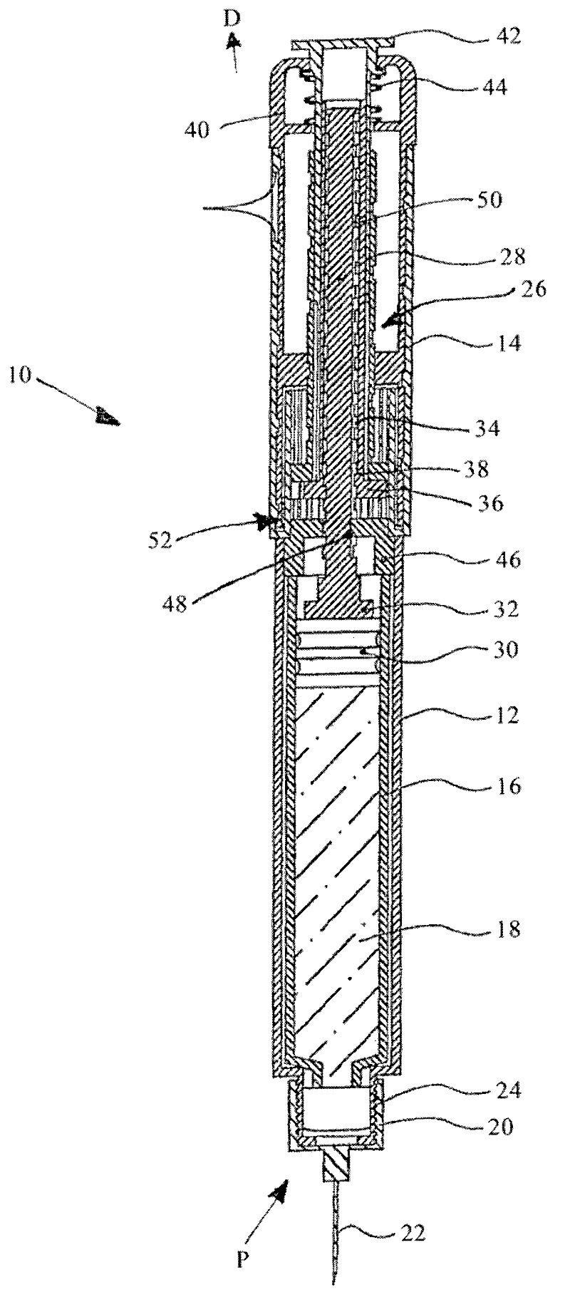
[0033] figure 1 is a longitudinal cross-sectional view of the injection device 10 comprising a proximal housing portion 12 and a distal housing portion 14 . Inside the proximal housing part 12, a container 16 filled with an injection fluid 18 is housed therein. On the proximal end P of the housing part 12, the cap 20 integrating the needle 22 is screwed thereon by the thread 24, so that the distal end of the needle 22 (not shown) is inserted into the container 16 for the injection fluid 18. Provide export.

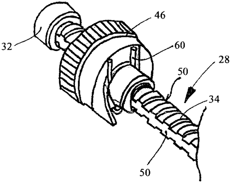
[0034] The distal housing part 14 comprises a dose setting and injection mechanism 26 which is described in detail in document EP 1 610 848 B1. The injection mechanism 26 includes a piston rod 28 that is axially movable relative to the housings 12 , 14 to dispense the injection fluid 18 from the container 16 via a piston 30 that contacts a proximal end 32 of the piston rod 28 . The piston rod 28 has an external thread 34 and is arranged to resist torque relative to the ...


PUM


Abstract

The invention relates to a injection device, comprising a housing being adapted to receive in its proximal housing portion a container with an injection fluid and to receive in its distal housing portion a dose setting and injection mechanism, wherein the mechanism includes a piston rod (28) being axially displaceable with respect to the housing for dispensing injection fluid from the container, wherein the piston rod (28) has an outer thread (34) and is arranged torque proof with respect to the housing, dose setting means comprising a threaded element, which threaded element has an inner thread being in engagement with the outer thread (34) of the piston rod (28), is designed so that its axial position relative to the housing is changeable and is rotatable relative to the piston rod (28) and relative to the housing during setting of an injection dose, wherein the dose setting means are designed such that the threaded element is held in torque proof manner relative to the piston rod (28) and to the housing during the injection of the beforehand set injection dose in such a manner that the threaded element and the piston rod (28) are axially displaceable together with respect to the housing, wherein the mechanism (26) further comprises holding means (60; 160) being in contact with the piston rod (28) and being designed such that the axial displacement of the piston rod (28) can be substantially immobilized during use of the device except for the dispensing of the injection dose. It is proposed according to the invention that the holding means (60; 160) are axially fixed with respect to the housing.

Description

technical field [0001] The present invention relates to an injection device comprising a housing arranged to receive a container with injection fluid in its proximal housing part and a dose setting and injection mechanism in its distal housing part, wherein the mechanism Comprising a piston rod axially movable relative to the housing for dispensing injection fluid from the container and dose setting means comprising a threaded element, the piston rod having an external thread and arranged to resist the torque of the housing , while the threaded element includes an inner thread that engages with the outer thread of the piston rod, the dose setting device is designed such that its axial position relative to the housing is variable, and when setting the injected dose is rotatable relative to the piston rod and housing, wherein the dose setting device is designed such that the threaded element is held against torque relative to the piston rod and housing when injecting a pre-set i...

Claims


Application Information

Patent Timeline
IPC IPC(8): A61M5/315
CPCA61M5/31535A61M5/31551A61M2005/3152A61M5/31585A61M5/31558A61M2005/3151A61M2205/583A61M2005/2488A61M5/24A61M2005/2407A61M5/31505A61M5/178A61M5/315A61M5/31501A61M5/31536
Inventor 迈克尔.沙巴赫阿克塞尔.罗思格哈德.汉布雷克特
Owner SANOFI AVENTIS DEUT GMBH
Why Eureka
Try Eureka