
Centrifugal load application system

A centrifugal load and load technology, applied in the direction of machine gear/transmission mechanism testing, etc., can solve the problems of difficult installation, asynchronous loading, difficult parts fatigue life test, etc., to achieve accurate and effective control, safe and reliable operation, and increase centrifugal load. Effect

Active Publication Date: 2013-06-19
CHINA AVIATION POWER MACHINE INST
View PDF6 Cites 0 Cited by
  • Summary
  • Abstract
  • Description
  • Claims
  • Application Information

AI Technical Summary

Problems solved by technology

[0003] According to the usual practice, it is necessary to use one-way actuators with the same number as the number of blades to simulate the applied centrifugal load. Due to the limited space size of the blades, not only will it cause difficulty in installation, but also it is easy to cause asynchronous loading during loading control. Difficult to achieve coordinated application with other types of loads
Therefore, it is difficult to carry out the fatigue life test of such parts smoothly by using the conventional test loading method

Method used


Image

  • Centrifugal load application system
  • Centrifugal load application system
  • Centrifugal load application system

Examples


Embodiment Construction

[0022] It should be noted that, in the case of no conflict, the embodiments of the present invention and the features in the embodiments can be combined with each other. The present invention will be described in detail below with reference to the accompanying drawings and examples.

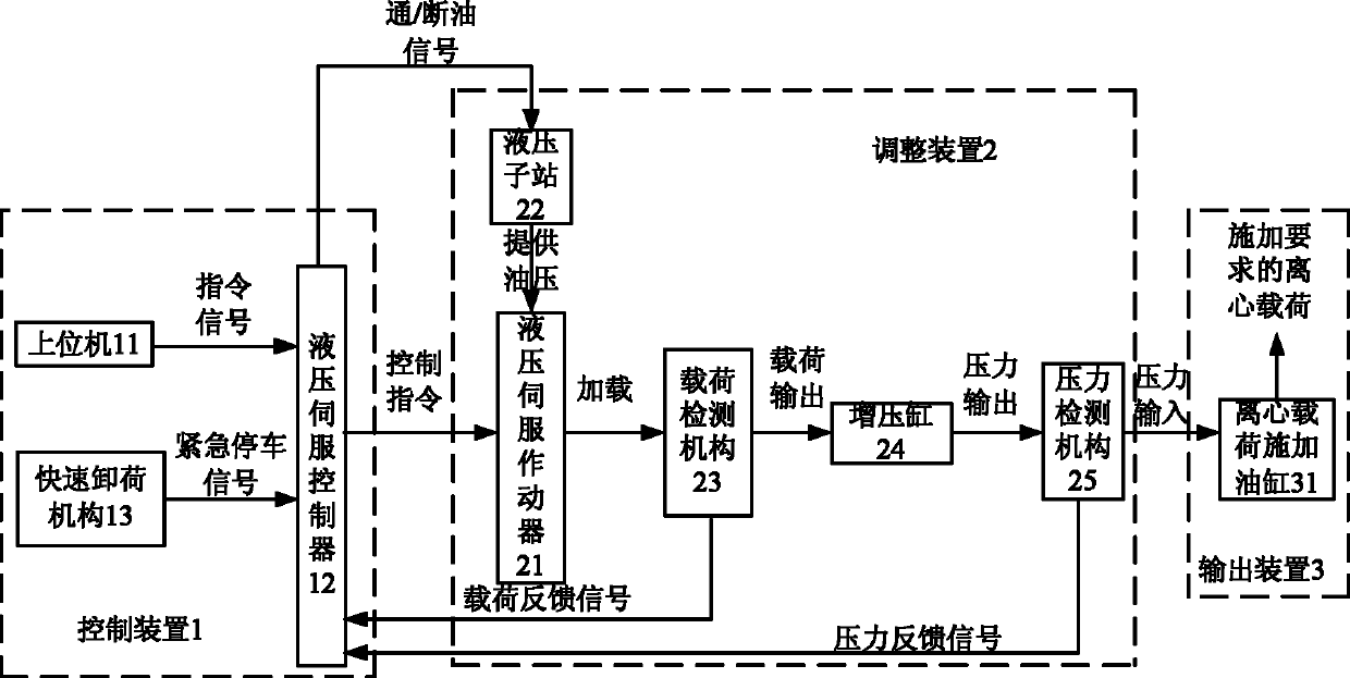
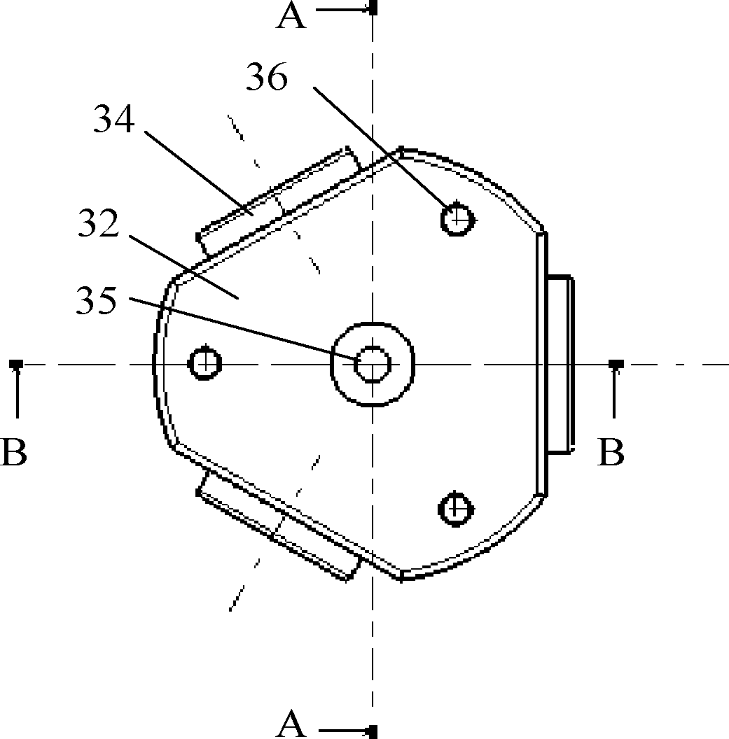
[0023] Such as figure 1 , figure 2 , image 3 , Figure 4 with Figure 5 As shown, the centrifugal load application system according to the present invention includes a control device 1 for issuing a control command; an adjustment device 2 for adjusting the output load according to the command issued by the control device 1; an output device 3 for receiving the adjustment device 2 The output load, and the multi-directional load is applied synchronously to the inner cavity of the part to be tested. The output device 3 includes a centrifugal load applying oil cylinder 31, which has a plurality of output shafts for synchronously applying centrifugal loads. In this embodiment, since it is mainl...


PUM


Abstract

The invention provides a centrifugal load application system. The system comprises a control device (1), an adjustment device (2) and an output device (3), wherein the control device (1) is used for sending a control command; the adjustment device (2) adjusts an output load according to the command sent by the control device (1); and the output device (3) receives the output load of the adjustment device (2), and synchronously applies multi-directional loads to an inner cavity of a component to be detected. According to the centrifugal load application system, a centrifugal load application cylinder can be easily arranged in the inner cavity of the component to be detected, and the multi-directional synchronous loads can be applied to the inner cavity of the component to be detected. The centrifugal load application system has high load application accuracy, and is convenient to operate and control, and safe and reliable to use.

Description

technical field [0001] The invention relates in particular to a centrifugal load application system. Background technique [0002] The key part of the helicopter tail transmission system - the tail rotor shaft is processed and formed by the electron beam welding of the main shaft and the hub part. In order to test the fatigue life of this type of parts, in addition to applying conventional rotational bending moment, axial force, torque, shear force and other loads to the tail rotor shaft, it is also necessary to apply centrifugal loads. The centrifugal load is generated by the helicopter tail blades, the number is the same as the number of blades, and the circumferential direction is evenly distributed. Due to the complex flight conditions of helicopters, the centrifugal load also changes with different flight conditions. [0003] According to the usual practice, it is necessary to use one-way actuators with the same number as the number of blades to simulate the applied c...

Claims


Application Information

Patent Timeline
Patent Type & Authority Patents(China)
IPC IPC(8): G01M13/02
Inventor 林利胜高洁陈昌根王亮
Owner CHINA AVIATION POWER MACHINE INST
Learn More