Suction hood

The technology of a suction hood and a suction device, which is applied in the field of suction hoods, can solve problems such as low efficiency and achieve the effect of improving suction characteristics

Active Publication Date: 2011-11-30
ELECTROLUX HOME PROD CORP NV
View PDF7 Cites 23 Cited by
  • Summary
  • Abstract
  • Description
  • Claims
  • Application Information

AI Technical Summary

Problems solved by technology

[0006] Traditional hoods like the ones above are relatively inefficient at least when deal

Method used


Image

  • Suction hood
  • Suction hood
  • Suction hood

Examples


Embodiment Construction

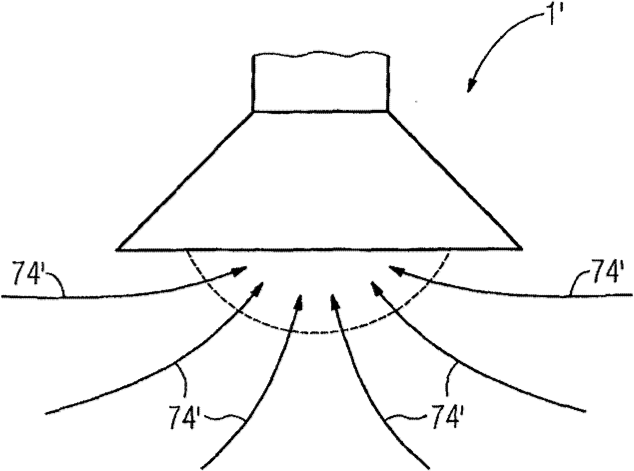
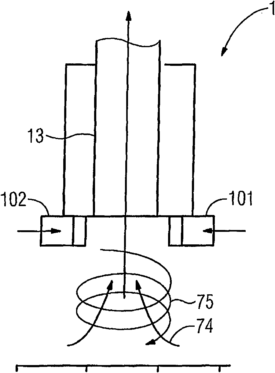
[0036] Figure 1c The concept of the cyclone suction hood 1 is briefly shown. Arrow 75 indicates a rotating air column and arrow 74 indicates suction ventilation. The combination of these two flows creates a cyclone. Air is sucked in through the air inlets 101 , 102 and thus pushed into the suction channel 13 .

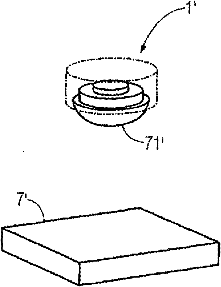
[0037] Figure 1d The pressure field 71 of such a hood system 1 is shown in . The pressure field represents the effective suction volume of the hood. The vortex created between the cooktop 7 and the hood 1 will draw the smoke from the cooktop 7 in a spiral motion.

[0038] figure 2 A suction hood 1 according to the invention is shown, which is arranged in a housing 18 . A vortex generator 10 is arranged at the lower end of the housing 18, and suction channels 131, 130 extend from the vortex generator to an opening at the top. In the lower part 131 , the suction channel has an upwardly narrowing conical shape, whereas in the upper part 130 the suction channel ...


PUM


Abstract

The invention relates to a sucking means (10, 20, 30, 40, 50), preferably vortex generator or tornado suction means, preferably for a suction hood, a) which pulls the air into a suction hood (1, 2, 3, 4, 5) by generating an at least substantially circular, cyclone, vortex or helix movement, b) wherein the sucking means (10, 20, 30, 40, 50) comprises a, preferably ring shaped, area (17, 27, 37, 47, 57) with at least substantially tangential channels (172, 272, 372, 472) and/or channels (172, 272, 372, 472) with a tangential component which are separated from each other by separating elements (171), preferably blades, for generating the at least substantially circular, cyclone, vortex or helix movement, a suction hood and a method for generating an air suction by means of a suction hood.

Description

technical field [0001] The invention relates to a suction hood which sucks air from a first area to a second area. Background technique [0002] Known or conventional extraction hoods (which may also be referred to as incinerator hoods, range hoods, kitchen hoods, stove hoods, exhaust hoods, cooker hoods, extraction hoods, exhaust hoods or ventilation hoods) are used for A combination of filtration and extraction of air to remove airborne grease, combustion products, smoke, odors and / or heat and vapor typically generated on cooktops by the cooking process. Extraction hoods typically consist of three main components: a skirt or capture panel to contain the rising gas (also known as the "exhaust plume"); one or more grease filters; and a fan or cutout for forced ventilation. To the hair dryer. [0003] The extractor hood serves two main purposes: ventilation and recirculation. In ventilation applications, the output collar of the blower motor of the extractor hood is mounte...

Claims


Application Information

Patent Timeline
IPC IPC(8): F24C15/20
CPCF24C15/20F24F7/06
Inventor F·科莱奥尼C·D·卡塔罗格内
Owner ELECTROLUX HOME PROD CORP NV
Why Eureka
Try Eureka