Liquid crystal display device

一种液晶显示装置、像素的技术,应用在辨认装置、静态指示器、光学等方向,能够解决成本增大、生产成品率降低等问题

Inactive Publication Date: 2011-11-30
SHARP KK
View PDF12 Cites 8 Cited by
  • Summary
  • Abstract
  • Description
  • Claims
  • Application Information

AI Technical Summary

Problems solved by technology

[0007] In order to make the luminance of the regions in the sub-pixels different, it is necessary to form fine electrodes corresponding to the regions of the sub-pixels, which raises the cost and reduces the production yield.

Method used


Image

  • Liquid crystal display device
  • Liquid crystal display device
  • Liquid crystal display device

Examples


Embodiment approach 1

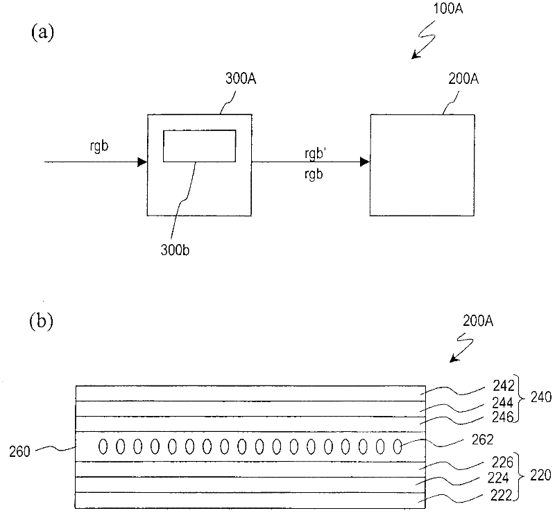
[0090] Hereinafter, a first embodiment of the liquid crystal display device of the present invention will be described. figure 1 (a) shows the schematic diagram of 100 A of liquid crystal display devices of this embodiment. The liquid crystal display device 100A includes a liquid crystal display panel 200A and a correction unit 300A. The liquid crystal display panel 200A includes a plurality of pixels arranged in a matrix of rows and columns. Here, a pixel has red, green, and blue sub-pixels in the liquid crystal display panel 200A. In the following description of this specification, a liquid crystal display device may also be simply referred to as a "display device".

[0091] The correcting unit 300A corrects at least one grayscale level or corresponding luminance level of the red, green and blue sub-pixels represented by the input signal under certain conditions, and does not perform correction under other conditions. Here, the correcting unit 300A has a blue correcting u...

Embodiment approach 2

[0227] In the above description, each sub-pixel exhibits one luminance, but the present invention is not limited thereto. It is also possible to adopt a multi-pixel structure, and each sub-pixel has a plurality of regions for obtaining different luminance.

[0228] Below, refer to Figure 27 , the second embodiment of the liquid crystal display device of the present invention will be described. The liquid crystal display device 100B of this embodiment includes: a liquid crystal display panel 200B; and a correction unit 300B. Here, the correction unit 300B also has a blue correction unit 300b. In the liquid crystal display device 100B, each sub-pixel in the liquid crystal display panel 200B has a region where different luminance is obtained, and the effective potential of the separation electrode that defines the region where different luminance is obtained changes according to a change in the potential of the storage capacitor wiring. , has the same configuration as the liq...

Embodiment approach 3

[0245] In the above description, two sub-pixels belonging to two adjacent pixels are used as a unit to adjust the luminance, but the present invention is not limited thereto. It is also possible to adjust the brightness of different regions belonging to one sub-pixel as a unit.

[0246] Below, refer to Figure 30 , the third embodiment of the liquid crystal display device of the present invention will be described. The liquid crystal display device 100C of this embodiment includes: a liquid crystal display panel 200C; and a correction unit 300C. Here, the correcting unit 300C has a blue correcting unit 300b. The liquid crystal display device 100C is similar to the liquid crystal display device of Embodiment 1 above in that each sub-pixel in the liquid crystal display panel 200C has a region for obtaining different luminance and that two source lines are provided for one column of sub-pixels. For the same structure, repeated descriptions are omitted to avoid redundancy.

[...


PUM


Abstract

The liquid crystal display device of the present invention includes a first pixel ( P1 ) and a second pixel ( P2 ) adjacent to each other in the row direction. When the input signal shows the first color (achromatic), the blue correction unit (300b) corrects the grayscale level b of the blue sub-pixel to the grayscale level b', so that the first pixel (P1) The brightness of the third sub-pixel (B1) is different from the brightness of the third sub-pixel (B2) of the second pixel (P2). In the case where the input signal shows the second color (blue), the brightness of the third sub-pixel (B1) of the first pixel (P1) is approximately equal to the brightness of the third sub-pixel (B2) of the second pixel (P2) . The average of the brightness of the third sub-pixel (B1) of the first pixel (P1) and the brightness of the third sub-pixel (B2) of the second pixel (P2) in the case where the input signal shows the first color (achromatic color) It is approximately equal to the above average in the case where the input signal shows the second color (blue). According to the present invention, it is possible to provide a liquid crystal display device capable of improving viewing angle characteristics and suppressing a decrease in display quality.

Description

technical field [0001] The present invention relates to a liquid crystal display device. Background technique [0002] Liquid crystal display devices are used not only as large televisions but also as small display devices such as display units of mobile phones. In the currently widely used color liquid crystal display devices, a pixel is composed of sub-pixels corresponding to the three primary colors of light of red (R), green (G), and blue (B), and is typically realized by a color filter. The colors of the red, green and blue sub-pixels are different. [0003] In the prior art, a TN (Twisted Nematic: twisted nematic) mode liquid crystal display device is used, but since the viewing angle of the TN mode liquid crystal display device is relatively narrow, in recent years, IPS (In-Plane-Switching: In-plane switching) mode and VA (Vertical Alignment: vertical alignment) mode and other liquid crystal display devices with wide viewing angles. In such a mode with a wide viewi...

Claims


Application Information

Patent Timeline
Patent Type & Authority Applications(China)
IPC IPC(8): G02F1/133G02F1/1337G09F9/30G09G3/20G09G3/36
CPCG09G2320/0271G02F2201/52G09G2340/06G09G2320/0285G09G2300/0452G09G2340/0457G09G2320/0242G09G2300/0443G09G3/3648G09G2320/068G09G3/3607G02F1/13306G09G3/2074G02F1/133G09G3/36
Inventor 森智彦富泽一成吉田悠一
Owner SHARP KK
Why Eureka
Try Eureka