
Electropneumatic towing module for rail vehicles

A rail vehicle and electric signal technology, applied in the field of rail vehicles, can solve the problems of large investment and high cost of brakes, and achieve the effect of improving safety

Inactive Publication Date: 2013-12-25
SIEMENS AG
View PDF3 Cites 0 Cited by
  • Summary
  • Abstract
  • Description
  • Claims
  • Application Information

AI Technical Summary

Problems solved by technology

However, setting the indirect brake on the lower layer requires a large investment and high cost

Method used


Image

  • Electropneumatic towing module for rail vehicles
  • Electropneumatic towing module for rail vehicles
  • Electropneumatic towing module for rail vehicles

Examples


Embodiment Construction

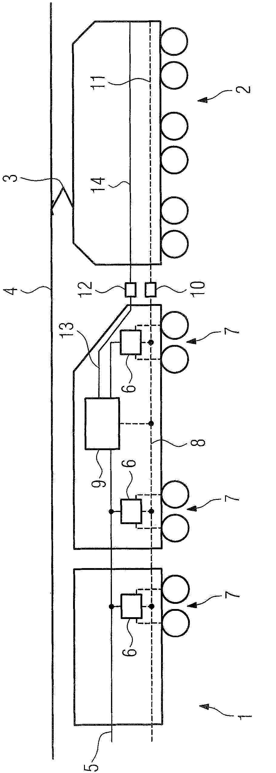
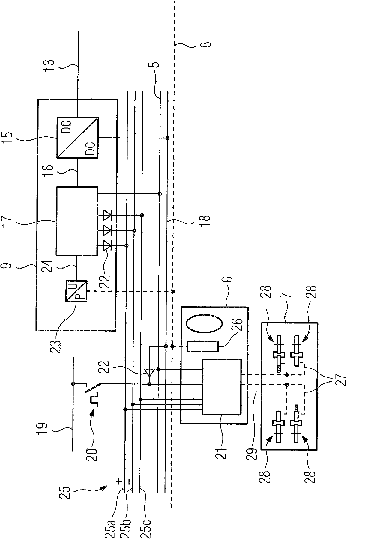
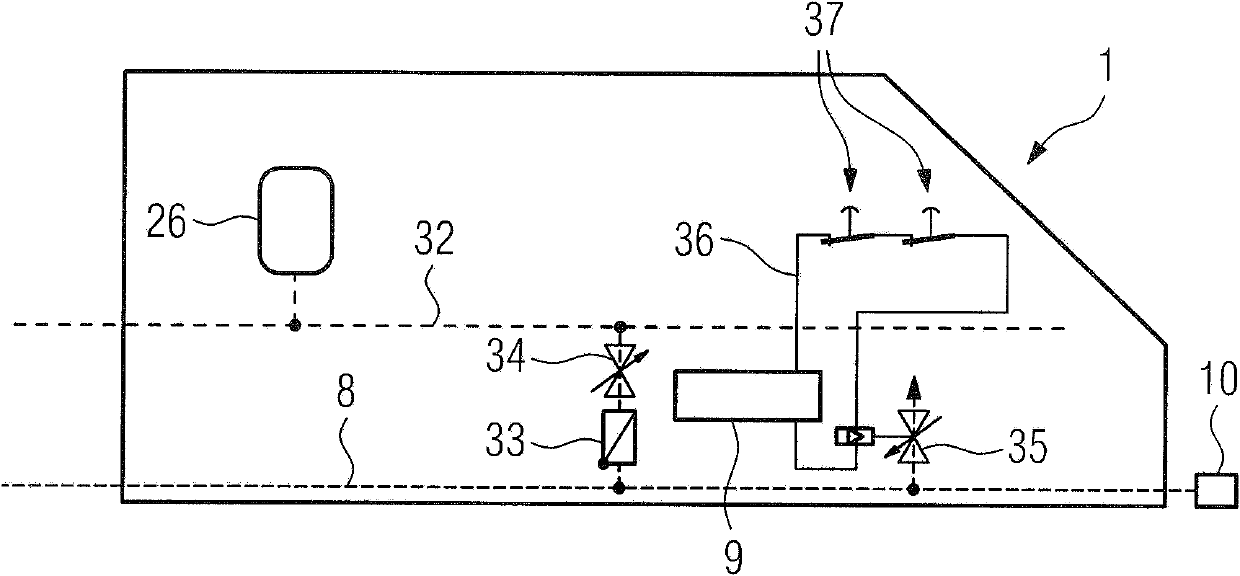
[0029] figure 1 An exemplary embodiment of a rail vehicle 1 according to the invention is shown which is towed by a locomotive 2 as traction rail vehicle. The current collector 3 of the locomotive 2 is connected with the overhead wire 4 that provides electric energy. In contrast, the rail vehicle 1 does not have its own electrical energy supply. The brake system used in normal operation of the rail vehicle 1 is an electro-pneumatic brake system, wherein the desired value is transmitted as an electrical signal via a serial data bus 5, in other words an operating signal line, to the brake module 6, which The dynamic modules correspond to the steering chassis 7 of the rail vehicle 1, respectively. The modular brake controller 6 is also supplied with compressed air via the main tank air line 8 , wherein via the serial data bus 5 the controllable valves in the brake cylinders, not shown in the drawing, depend on the above-mentioned setpoint value adjustment mechanism. The dynami...


PUM


Abstract

The towing module (9) comprises a fluid pressure line (8,32) for connecting with a fluid connection, which is arranged for driving a fluid with pressure, and an electrical connector for connecting an electric supply line (13) impinged with electrical supply voltage. A converter (23) is provided, which is connected with the fluid connection. An independent claim is also included for a rail vehicle comprises a towing module.

Description

technical field [0001] The invention relates to a traction module for a rail vehicle and to a rail vehicle having such a traction module. Background technique [0002] In the event of a complete failure of a rail vehicle, it must be towed as quickly as possible in order to be able to quickly clear the otherwise blocked lanes and resume planned rail traffic. When towing, the braking power for all vehicle attachments of the towing vehicle is usually transmitted separately. The pulling process must then be carried out at very low speeds, in particular in the case of longer connections, in order to comply with the respective critical safety requirements. [0003] Electropneumatic brakes, also known as direct brakes, are known from practice and are supplemented by indirect pneumatic brakes. Indirect brakes do not require electrical energy for forming and controlling the braking process, but are powered and controlled by compressed air. The braking power is controlled by means ...

Claims


Application Information

Patent Timeline
Patent Type & Authority Patents(China)
IPC IPC(8): B60T13/66B61H11/06
CPCB61C17/00B60T17/228B60T13/665
Inventor 比尔吉特·布拉德
Owner SIEMENS AG
Learn More