Supercharge Your Innovation With Domain-Expert AI Agents!

The sealing structure of the shaft sleeve and the mounting seat

A sealing structure and mounting seat technology, which is applied to the sealing of the engine, the rigid support of the bearing components, the bearing components, etc., can solve the problem of dust and other sundries entering the working area of ​​the shaft, etc.

Inactive Publication Date: 2011-12-14
ZHANGJIAGANG LANHANG MACHINERY
View PDF5 Cites 0 Cited by
  • Summary
  • Abstract
  • Description
  • Claims
  • Application Information

AI Technical Summary

Problems solved by technology

The disadvantage of the above connection structure is that since the inner wall of the mounting seat hole and the outer wall of the shaft sleeve are both smooth, there will inevitably be a certain gap during installation, and dust and other sundries will easily enter the working area of ​​the shaft through the gap

Method used


Image

  • The sealing structure of the shaft sleeve and the mounting seat
  • The sealing structure of the shaft sleeve and the mounting seat
  • The sealing structure of the shaft sleeve and the mounting seat

Examples


Embodiment Construction

[0009] The sealing structure of the shaft sleeve and the mounting seat of the present invention will be further described in detail through specific embodiments below.

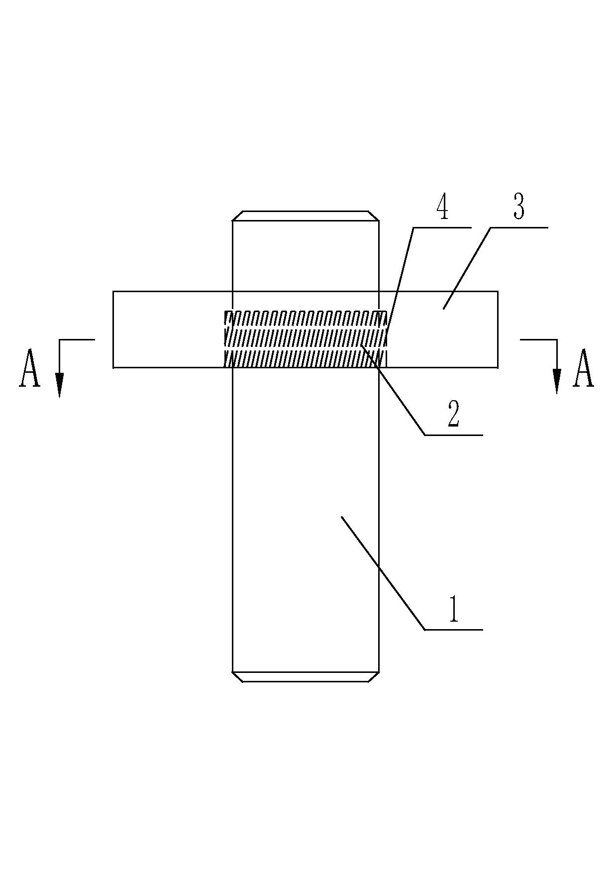
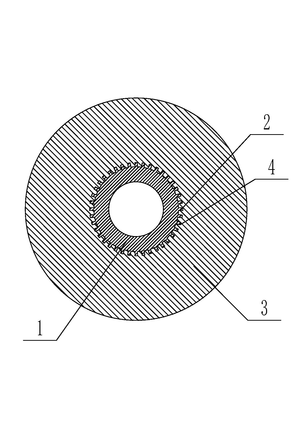
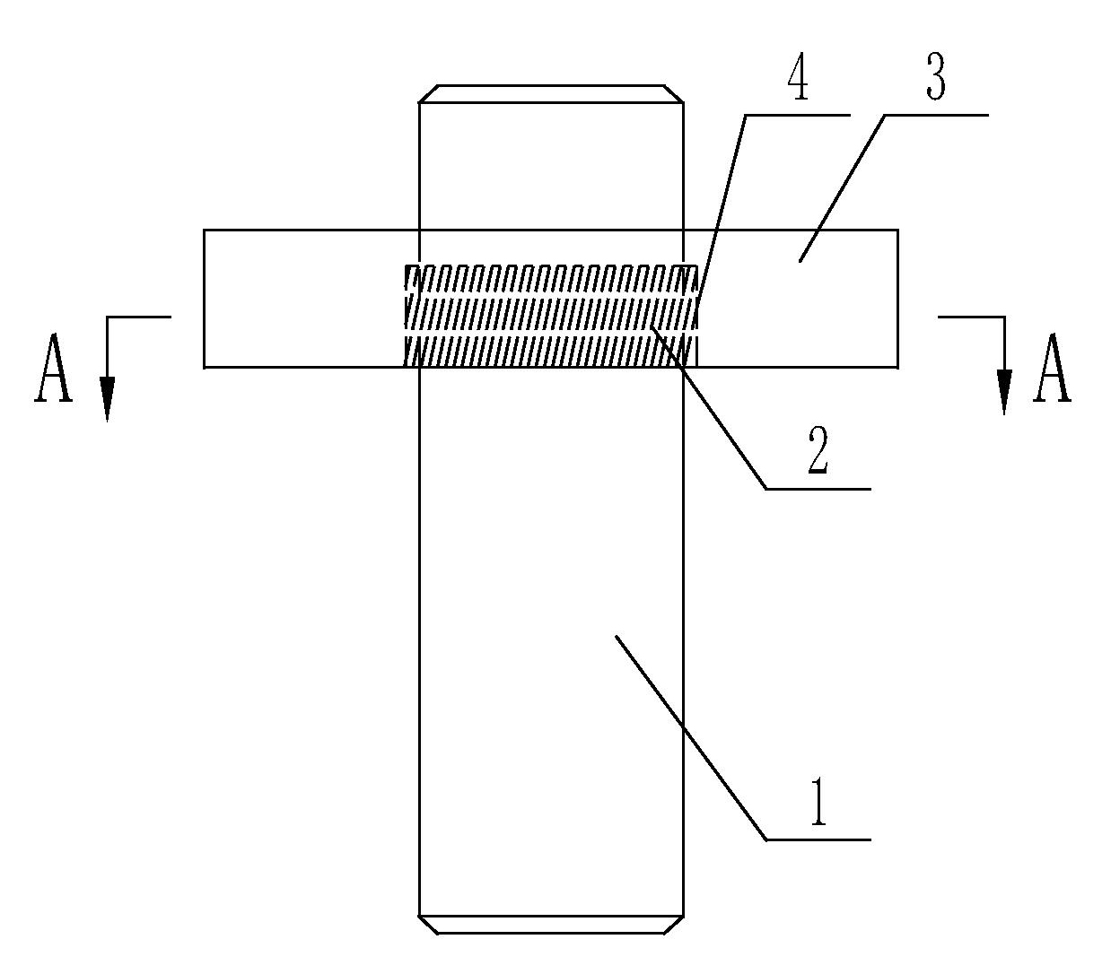
[0010] like figure 1 , figure 2 As shown in the sealing structure of the shaft sleeve and the mounting seat, the outer wall of the shaft sleeve 1 is provided with several helical teeth 2 along the ring direction, and the helical teeth 2 are arranged parallel to each other; the inner wall of the mounting seat 3 is provided with several oblique teeth along the ring direction. The tooth groove 4 and the helical tooth groove 4 are arranged parallel to each other. When installing, place the front end of the helical tooth 2 of the bushing 1 on the helical tooth groove 4 of the mounting seat 3, and then rotate the bushing 1 so that the helical tooth 2 is aligned with the helical tooth groove 4. The tooth grooves 4 are engaged with each other.

[0011] The beneficial effects of the present invention are: the above-...


PUM


Abstract

The invention relates to a sealing structure of a shaft sleeve and a mounting seat. The outer wall of the shaft sleeve is provided with several helical teeth along the ring direction, and the helical teeth are arranged parallel to each other; the inner wall of the mounting seat is provided with several helical tooth grooves along the ring direction. , the helical tooth grooves are arranged parallel to each other, and the helical tooth grooves and the helical teeth are meshed and connected with each other. The invention is suitable for the sealing connection between the shaft sleeve and the mounting seat, and can prevent dust and other sundries from easily entering the working area of ​​the shaft.

Description

technical field [0001] The invention relates to a sealing structure of a shaft sleeve and a mounting seat. Background technique [0002] The shaft sleeve is sleeved on the outside of the rotating shaft, which plays a role in positioning or protecting the rotating shaft. For example, a shaft sleeve is used between the shaft and the mounting seat, which can prevent the shaft from being damaged due to direct friction with the mounting seat when rotating, so that the shaft rotates inside the shaft sleeve when rotating, and the shaft sleeve is replaced when it is worn, which is low in cost. Most of the shaft sleeves currently used are cylindrical structures with smooth inner and outer walls. When in use, the rotating shaft is arranged inside the shaft sleeve, and a hole with a smooth inner wall is arranged in the mounting seat, and the shaft sleeve is arranged in the hole of the mounting seat. The key is also clamped between the inner wall of the mounting seat and the outer wall...

Claims


Application Information

Patent Timeline
IPC IPC(8): F16J15/447F16C35/02
Inventor 黄振芳黄晓燕
Owner ZHANGJIAGANG LANHANG MACHINERY
Features
  • R&D
  • Intellectual Property
  • Life Sciences
  • Materials
  • Tech Scout
  • Unparalleled Data Quality
  • Higher Quality Content
  • 60% Fewer Hallucinations
Learn More