Escalator transmission mode and device by utilizing gravitational potential energy of human body

An escalator and gravitational potential energy technology, applied in escalators, transportation and packaging, etc., can solve the problems of high cost, escalator life loss, and general energy-saving effect, and achieve the goal of reducing manufacturing costs, saving costs, and saving power system costs Effect

Inactive Publication Date: 2011-12-21
EAST CHINA UNIV OF SCI & TECH
View PDF5 Cites 7 Cited by
  • Summary
  • Abstract
  • Description
  • Claims
  • Application Information

AI Technical Summary

Problems solved by technology

The former scheme requires the escalator to start and stop frequently or change speed, which seriously damages the life of the escalator; the latter can realize the use of the gravitational potential energy of the crowd, but requires a power generation device, which is costly and generally energy-saving.
[0004] At present, there is no technology that can directly connect two parallel escalators, release the gravitational potential energy of the crowd carried by the downward escalator to the upward escalator in real time, and realize the full use of the gravitational potential energy of the descending crowd through the reform of the transmission mechanism

Method used


Image

  • Escalator transmission mode and device by utilizing gravitational potential energy of human body
  • Escalator transmission mode and device by utilizing gravitational potential energy of human body
  • Escalator transmission mode and device by utilizing gravitational potential energy of human body

Examples


Embodiment 1

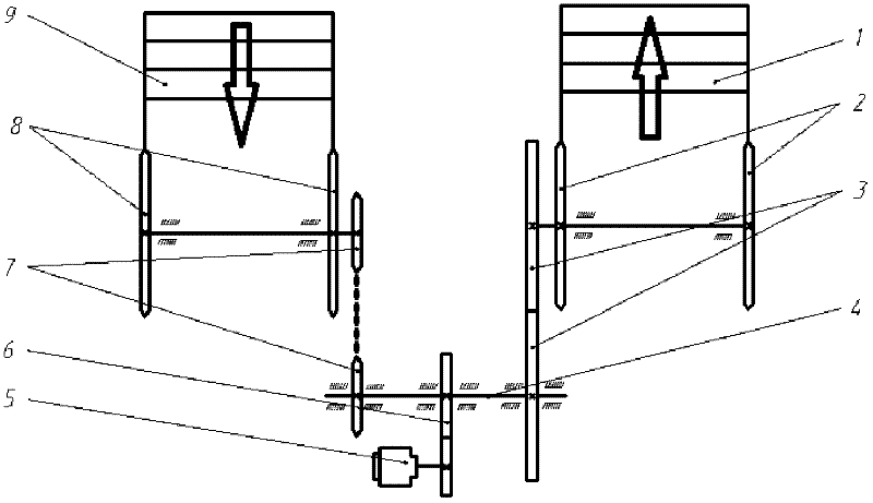
[0016] Such as figure 1 As shown, the escalator power transmission mechanism designed according to the above scheme is suitable for occasions where the distance between two parallel escalators is relatively large, and the motor and the transmission device are located between the two elevators. 1 is an upward elevator, and 2 is a drive sprocket that drives the elevator to run. 3 is the transmission gear that transmits power to the elevator. 4 is the power spindle that provides elevator power. 5 is the motor that provides the power for the main shaft. 6 is the transmission gear between the motor and the power main shaft. 7 is a transmission sprocket provided to the descending elevator 9 from the power main shaft, which makes the running direction of the descending elevator 9 and the upward elevator 1 exactly opposite. 8 is a drive sprocket that drives the downward elevator 9 to run.

[0017] Only the drive sprocket 7 is a newly added device in this scheme, which connects the do...

Embodiment 2

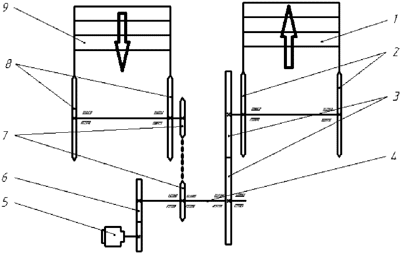
[0020] Such as figure 2 As shown, the escalator power transmission mechanism designed according to the above scheme is suitable for the occasions where the distance between two parallel escalators is small. Since the two elevators are closely placed, the newly added transmission device driven by the upward elevator 1 is added in this scheme. The driving sprocket 7 of the descending elevator 9 is relatively close to the driving gear 3 of the ascending elevator, and the motor 5 that provides the power main shaft 4 for operation and the transmission gear 6 that transmits power from the motor to the power main shaft 4 are located on the same side of the power main shaft. The upward elevator 1, the sprocket 2 that drives the upward elevator to run, and the transmission gear 3 of the upward elevator remain unchanged. Similarly, for the descending elevator 9, the driving sprocket 8 that drives the descending elevator to run remains unchanged.


PUM


Abstract

The invention relates to an escalator transmission mode and an escalator transmission device by utilizing the gravitational potential energy of a human body. The escalator transmission mode is a method capable of fully utilizing reduced potential energy due to the reduced gravity center of a people stream on a down-escalator; transmission mechanisms of an up-escalator and a down-escalator are combined, the potential energy released due to the reduced potential energy of the down people is balanced with the potential energy required by lifting a people stream on the up-escalator, and insufficient energy is provided by a transmission device. The invention solves the transmission problem that one set of transmission device cannot drive the up-escalator and the down-escalator to run positively and reversely, so that one set of transmission device can drives two automatic escalators running upwards and downwards. The potential energy released during downward running is fully utilized, a transmission device is saved and energy consumption is reduced.

Description

Technical field [0001] The invention relates to a power transmission method and device of an escalator using the gravity potential energy of the human body. The escalator provides a feasible transmission scheme by using the gravity potential energy of the descending crowd to save energy. This relates to a new type of escalator energy-saving power transmission structure and implementation Program. Background technique [0002] When the escalator is moving up, it needs work to lift the flow of people upstairs, but when it is going down, the potential energy of the flow of people is decreasing. This part of the energy is not used. Instead, it needs to provide power to run the downward elevator. Due to the huge flow of people in public places such as shopping malls, airports, and subway stations, the operation time is very long. This part of the energy accumulates into more energy, and it will be a big number. The present invention considers how to use the reduced potential energy ...

Claims


Application Information

Patent Timeline
Patent Type & Authority Applications(China)
IPC IPC(8): B66B23/02
Inventor 潘家祯暴术龙稽得宸闫阅潘海峰
Owner EAST CHINA UNIV OF SCI & TECH
Why Eureka
Try Eureka