Movable threading unit

A technology of drawing-in and drawing-in machine, which is applied to auxiliary equipment for weaving, fabrics, textiles, etc., can solve the problems of high initial cost, large capacity, unused utilization, etc., and achieve the effect of low cost

Inactive Publication Date: 2011-12-21
普费菲孔斯陶布里股份公司
View PDF8 Cites 15 Cited by
  • Summary
  • Abstract
  • Description
  • Claims
  • Application Information

AI Technical Summary

Problems solved by technology

Subsequent changes in the position of the drawing-in machine are only possible with considerable installation outlay and time

Method used


Image

  • Movable threading unit
  • Movable threading unit
  • Movable threading unit

Examples


Embodiment Construction

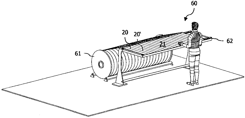
[0035] figure 1 A perspective view of the clamping unit 60 is shown in the ready position, said clamping unit comprising the warp thread layer 21 of the warp beam 61 inserted into said clamping unit. The generally stationary clamping unit 60 has a thread frame 62 rotatable in a vertical or horizontal line for clamping a warp thread layer 21 of individual warp threads 20 , 20 ′ coming from a warp beam 61 . The width corresponds at least to the widest warp thread layer 21 to be processed. The yarn frame 62 has a device for applying tension to the warp yarn layer 21 required for processing. The clamping unit 60 can be additionally provided with a support 70 for the reed on the side of the yarn frame 62, such as Figure 7 As shown in , each warp thread 20, 20 can be threaded into the reed simultaneously during the drawing-in process.

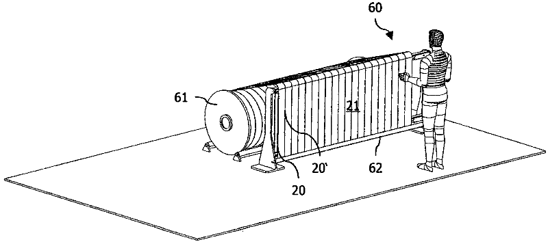
[0036] figure 2 show figure 2The clamping unit 60 is in the threading position for positioning the threading unit 10 according to the invent...


PUM


Abstract

The invention relates to a movable drawing-in unit (10) for threading individual warp threads (20) of a weaving warp thread into elements of a weaving implement, comprising: at least one feeding device (33, 43, 51) , in order to provide the elements of the weaving appliance; at least one receiving device (32, 42, 51) for receiving the elements of the weaving appliance with the threaded warp yarn (20); passing through the module (11) , the passing-through module is configured to separate an element from at least one providing device (33, 43), for grabbing a corresponding warp thread (20), for threading the warp thread (20) Into separate elements and for elements with threaded warp threads (20) to be positioned on a receiving device (32, 42), wherein for the threading of each warp thread (20), the threading unit (10) is movable in space.

Description

technical field [0001] The invention relates to a movable drawing-in unit according to claim 1 for threading warp threads of a weaving warp thread into elements of a weaving device, a drawing-in unit according to claim 10 comprising a fixed and A drawing-in machine of movable parts, a corresponding drawing-in method according to claim 12 and a preferred use of a drawing-in unit according to claim 15 . Background technique [0002] Before the weaving machine forms a fabric or textile material by joining warp threads and weft threads, the individual warp threads must be threaded into the weaving device in a defined arrangement. Usually heald frames, healds, drop wires and reeds belong to the elements of weaving equipment. Draw-in means that each individual warp thread (which is usually wound on a warp beam with the required length) is guided respectively through the drop wire, the heddle and between the two teeth of the reed. The guide eyelet of the gap, so that the ends of ...

Claims


Application Information

Patent Timeline
IPC IPC(8): D03J1/14
CPCD03J1/14D03D3/02
Inventor M·亨其克
Owner 普费菲孔斯陶布里股份公司
Why Eureka
Try Eureka