Supercharge Your Innovation With Domain-Expert AI Agents!

Cart pushing claw device

A pusher and push claw technology, which is applied to railway vehicle traction devices, transportation and packaging, railway car body components, etc., can solve problems such as potential safety hazards, damage to the transmission structure of pusher claw devices, and improve reliability. , Simple structure, flexible transmission mechanism

Inactive Publication Date: 2011-12-28
YANGZHOU KAISITE MACHINERY
View PDF0 Cites 1 Cited by
  • Summary
  • Abstract
  • Description
  • Claims
  • Application Information

AI Technical Summary

Problems solved by technology

[0003] Another kind of push claw device of the cart machine is to lift the push claw by touching the claw lifting mechanism with the touch block, but this kind of push claw device of the cart machine cannot pass through the claw lifting mechanism in reverse, if it is forced to pass through the claw lifting mechanism in reverse , the transmission structure of the push claw device of the cart machine will be damaged, causing potential safety hazards

Method used


Image

  • Cart pushing claw device
  • Cart pushing claw device

Examples


Embodiment Construction

[0013] The following describes the technical solution of the present invention in detail through a best embodiment in conjunction with the accompanying drawings, but the protection scope of the present invention is not limited to the embodiment.

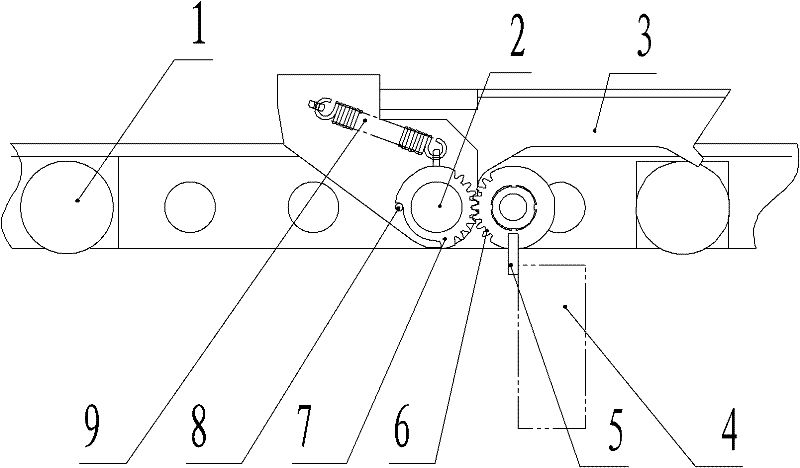
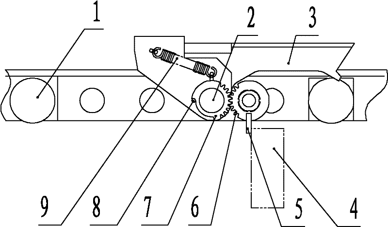
[0014] As shown in the figure, a push claw device for a cart machine includes a chain plate 1 of a push cart, a push claw 3, a driving gear 6 and a driven gear 7 provided with a bumper 5, and the push claw 3 and the driven gear 7 pass through The hinged shaft 2 is hinged with the chain plate 1 of the pushcart machine, the push claw 3 is provided with a limit pin 8 which limits the one-way rotation of the driven gear 7, the driven gear 7 is provided with a chute for the reverse sliding of the limit pin 8, and the driving gear 6 meshes with the driven gear 7, and the push claw 3 is provided with a tension spring 9 for the reset of the driven gear 7.

[0015] Working principle: The push claw device of the cart machine is moving forward....


PUM


Abstract

The invention discloses a push claw device for a cart machine. The pushing claw device of the cart machine comprises a chain plate (1) of the cart machine and a push claw (3), the claw (3) is hinged with the chain plate (1) of the cart machine through a hinge shaft (2), and also includes a bumper The driving gear (6) and the driven gear (7) of the block (5), the driven gear (7) is hinged with the push claw (3) through the hinge shaft (2), and the push claw (3) is provided with a limit driven gear ( 7) The limiting pin (8) rotates in one direction, and the driven gear (7) is provided with a chute for reverse sliding of the limiting pin (8), and the driving gear (6) meshes with the driven gear (7). The push claw device of the cart machine adopting the technical scheme can run bidirectionally, has a simple and compact structure, and is safe and reliable through trial use.

Description

technical field [0001] The invention relates to rail transportation equipment, in particular to a cart pushing claw device for pushing mine carts forward. Background technique [0002] The push claw device of the traditional trolley machine has a head-up type, that is, the push claw is lifted upwards through the counterweight or the tension spring, the chain plate of the cart machine moves forward to push the cart, and the axle or baffle of the mine cart presses down the push claw when moving backward. , The push claws are automatically reset through the mine car axle or the baffle. This structure only allows the mine car to move along the direction of the push claw cart, and does not allow the mine car to go backward. [0003] Another kind of push claw device of the cart machine is to lift the push claw by touching the claw lifting mechanism with the touch block, but this kind of push claw device of the cart machine cannot pass through the claw lifting mechanism in reverse,...

Claims


Application Information

Patent Timeline
IPC IPC(8): B61J3/12
Inventor 邹舰汪邦正翁刘基曹磊
Owner YANGZHOU KAISITE MACHINERY
Features
  • R&D
  • Intellectual Property
  • Life Sciences
  • Materials
  • Tech Scout
  • Unparalleled Data Quality
  • Higher Quality Content
  • 60% Fewer Hallucinations
Learn More