Multifunctional gastric lavage bed

A multi-functional, gastric lavage technology, applied in hospital beds, medical science, hospital equipment, etc., can solve problems such as inability to effectively reach the patient's vomit, the patient's inability to effectively maintain the lying position, splashing, etc.

Pending Publication Date: 2021-01-05
SHANGHAI PUDONG HOSPITAL
View PDF1 Cites 0 Cited by
  • Summary
  • Abstract
  • Description
  • Claims
  • Application Information

AI Technical Summary

Problems solved by technology

The invention is reasonable in structure, easy to operate, improves work efficiency, and saves labor. The patent only collects the patient's vomitus through the vomitus tank, which cannot effectively prevent the patient's vomitus from splashing, and the collected vomitus cannot be cleaned conveniently. The actual cleaning and maintenance of the equipment is extremely inconvenient, and the patent can only be maintained by the patient's own adjustment of the lying position, and the weaker patients cannot effectively maintain their own lying position, which affects the actual treatment effect. At the same time, the patent actually uses the height adjustment Cannot effectively fix the height of use, so that the actual use of the equipment is not good

Method used


Image

  • Multifunctional gastric lavage bed
  • Multifunctional gastric lavage bed
  • Multifunctional gastric lavage bed

Examples


Embodiment 1

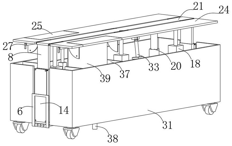
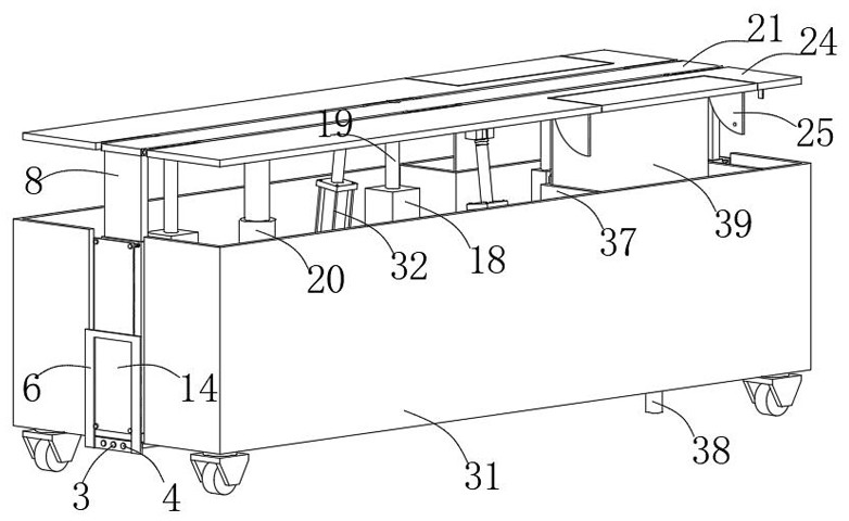
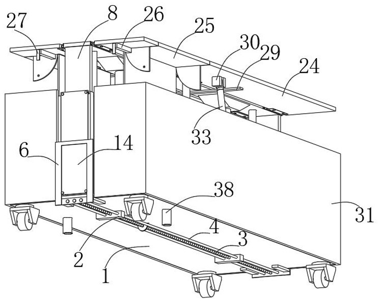
[0032] Embodiment one, with reference to Figure 1-12 : A multi-functional gastric lavage bed, comprising a base plate 1, the establishment of the base plate 1 provides the installation basis for other functional parts of the equipment, both sides of the center of the bottom of the base plate 1 are fixedly connected with a fixed block 2, and the setting of the fixed block 2 is convenient for sliding The installation and setting of the rod 4 and the two-way threaded rod 3, the two-way threaded rod 3 is slidingly embedded between the relative outer surfaces of the two fixed blocks 2, the establishment of the two-way threaded rod 3 facilitates the installation and setting of the extrusion plate 6, and can effectively carry out Effective adjustment of the actual use position of the extruding plate 6, the two-way threaded rod 3 is located between the opposite outer surfaces of the two fixed blocks 2, and both sides of the two-way threaded rod 3 have a sliding rod 4 running through i...

Embodiment 2

[0033] Embodiment two, refer to Figure 1-7 : The two ends of each slide bar 4 slide through the corresponding extrusion plate 6 respectively. The establishment of this structure enables the slide bar 4 to effectively limit the moving direction of the extrusion plate 6, and both ends of each slide bar 4 are fixedly connected The limit piece, the setting of the limit piece can effectively prevent the extruding plate 6 from breaking away from the two-way threaded rod 3, and the outer surface on one side of each push plate 14 and the outer surface on one side of the corresponding extruding plate 6 are all fitted, and each push plate 14 The outer surface of one side is all attached to one end of the corresponding four second springs 16. This structure enables the second springs 16 to effectively support the push plate 14 stably. The output end of the motor 17 is also sleeved with a pulley 5, two A belt is sleeved between the pulley 5 outer surfaces, and the bottom of the recliner ...

Embodiment 3

[0034] Embodiment three, refer to Figure 7-12 : the interior of each connecting pipe 38 is connected to the interior of the corresponding liquid collection frame 37, and the bottom end of each connecting pipe 38 extends to the bottom of the bottom plate 1. The establishment of this structure enables the equipment to be effectively connected with the existing storage equipment, and then To facilitate the convenient cleaning of vomit, the top of each splash guard 39 is attached to the bottom of the corresponding side plate 24, and the outer surface on one side of each splash guard 39 is attached to the inner surface wall on the corresponding side of the liquid collection frame 37. The establishment of this structure effectively prevents the patient's vomit from splashing around, so that the equipment can be easily maintained and cleaned.

[0035]When in use, by controlling the first air pressure rod 20, under the effective support of the support bar 29, the reclining board 21 c...


PUM


Abstract

The invention discloses a multifunctional gastric lavage bed. The multifunctional gastric lavage bed comprises a bottom plate, fixing blocks are fixedly connected to the two sides of the center of thebottom of the bottom plate, a two-way threaded rod is slidably embedded between the opposite outer surfaces of the two fixing blocks, sliding rods penetrate through the positions, located on the twosides of the two-way threaded rod, between the opposite outer surfaces of the two fixing blocks, extrusion plates are in threaded connection with the positions, located on the two sides of the bottomplate, of the outer surface of the two-way threaded rod, the position, close to the center, of the outer surface of the two-way threaded rod is sleeved with a belt wheel, and limiting frames are fixedly connected to the positions, close to the centers of the edges of the two sides, of the top of the bottom plate. According to the multifunctional gastric lavage bed, by controlling first air pressure rods, under effective supporting of supporting strips, a lying plate can drive side plates to effectively adjust the actual use height, then nursing personnel can easily move a patient to the top ofthe lying plate, the patient can effectively lie on the top of the equipment, and meanwhile, by starting a motor, the motor can effectively drive the two-way threaded rod to rotate through the belt wheel and a belt.

Description

technical field [0001] The invention belongs to the technical field of medical equipment, in particular to a multifunctional gastric lavage bed. Background technique [0002] Gastric lavage bed is a bedding used for patients to perform gastric lavage treatment, referring to Chinese patent CN105107046B: a multifunctional gastric lavage bed, including bed body, vomiting tank, head immobilizer, shoulder immobilizer, limbs and Body immobilizer, the bed body includes a bed board, and the bed board is sequentially designed with a head immobilizer and a shoulder immobilizer from top to bottom, and limbs and body immobilizers are respectively arranged on both sides of the bed board; The vomiting chute is located on the outside of the shoulder immobilizer. The invention is reasonable in structure, easy to operate, improves work efficiency, and saves labor. The patent only collects the patient's vomitus through the vomitus tank, which cannot effectively prevent the patient's vomitus ...

Claims


Application Information

Patent Timeline
Patent Type & Authority Applications(China)
IPC IPC(8): A61G7/047A61G7/002A61G7/05
CPCA61G7/002A61G7/047A61G7/05
Inventor 徐英瞿海红
Owner SHANGHAI PUDONG HOSPITAL
Why Eureka
Try Eureka