Single-period three-phase six-switch power factor correction PWM modulator

A technology of power factor correction and six switches, which is applied in the direction of output power conversion device, conversion of AC power input to DC power output, high-efficiency power electronic conversion, etc., can solve the problem of positive and negative asymmetry of sawtooth wave, which is troublesome and affects the effective application of technology and other problems, to overcome the influence of temperature characteristics and effectively promote the effect

Active Publication Date: 2020-03-31
WUHAN YONGLI TECH CO LTD
View PDF15 Cites 0 Cited by
  • Summary
  • Abstract
  • Description
  • Claims
  • Application Information

AI Technical Summary

Problems solved by technology

It is required to have a strict fixed relationship between the two, which means that a working frequency can only correspond to the integral parameter τ of a specific integrator. Once the working clock changes, the integral parameter of the integrator must change accordingly, otherwise it will Sawtooth wave is asymmetrical in positive and negative, or flat top occurs, resulting in large distortion
Because in practical application, the integral parameter of the integrator is determined by the integral resistance and the integral capacitance. Due to the temperature characteristics of the components, the operating frequency and the integral parameter will drift, and it is impossible to achieve a complete match.
And it is also necessary to fine-tune the maximum output of the integrator to be strictly equal to the input voltage of the integrator, so as to satisfy the restriction condition τ=0.5*T s , which is very cumbersome and time-consuming, so it will inevitably affect the effective application of the technology

Method used


Image

  • Single-period three-phase six-switch power factor correction PWM modulator
  • Single-period three-phase six-switch power factor correction PWM modulator
  • Single-period three-phase six-switch power factor correction PWM modulator

Examples


Embodiment Construction

[0033] In order to make the object, technical solution and advantages of the present invention clearer, the present invention will be further described in detail below in conjunction with the accompanying drawings and embodiments. It should be understood that the specific embodiments described here are only used to explain the present invention, not to limit the present invention. In addition, the technical features involved in the various embodiments of the present invention described below can be combined with each other as long as they do not constitute a conflict with each other.

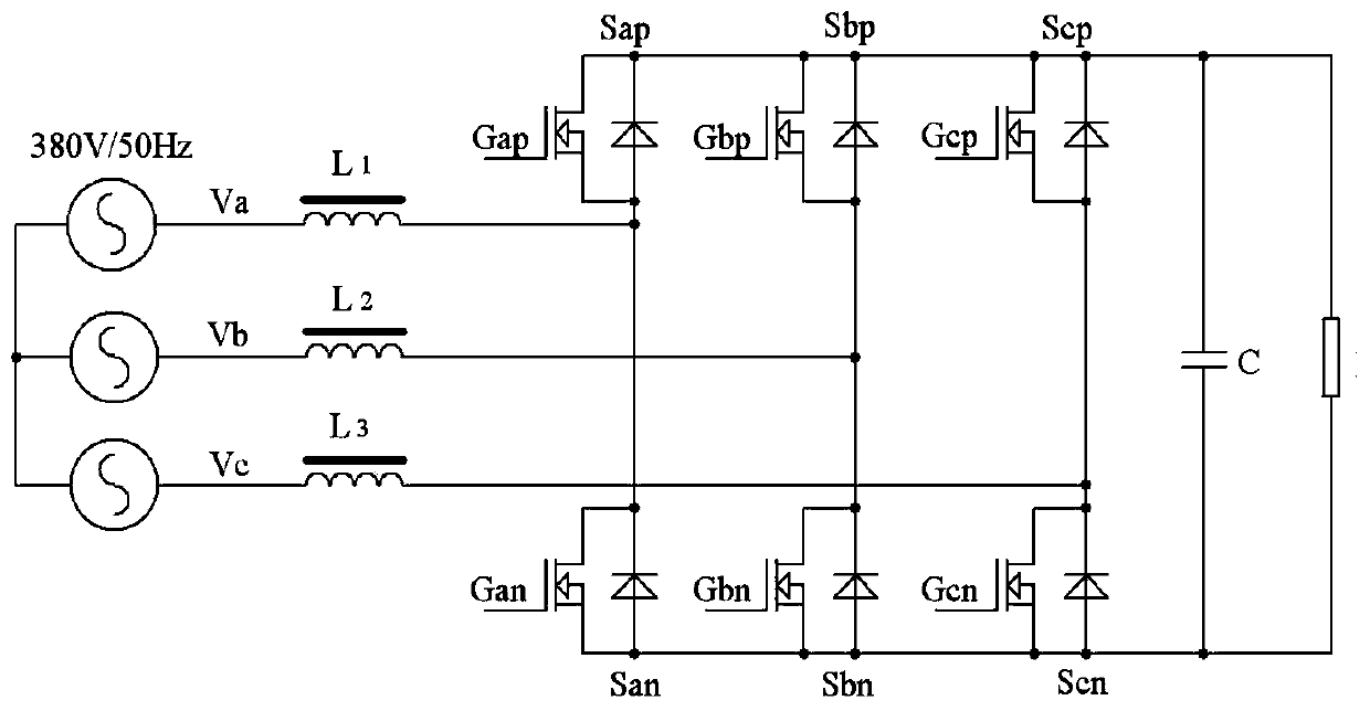
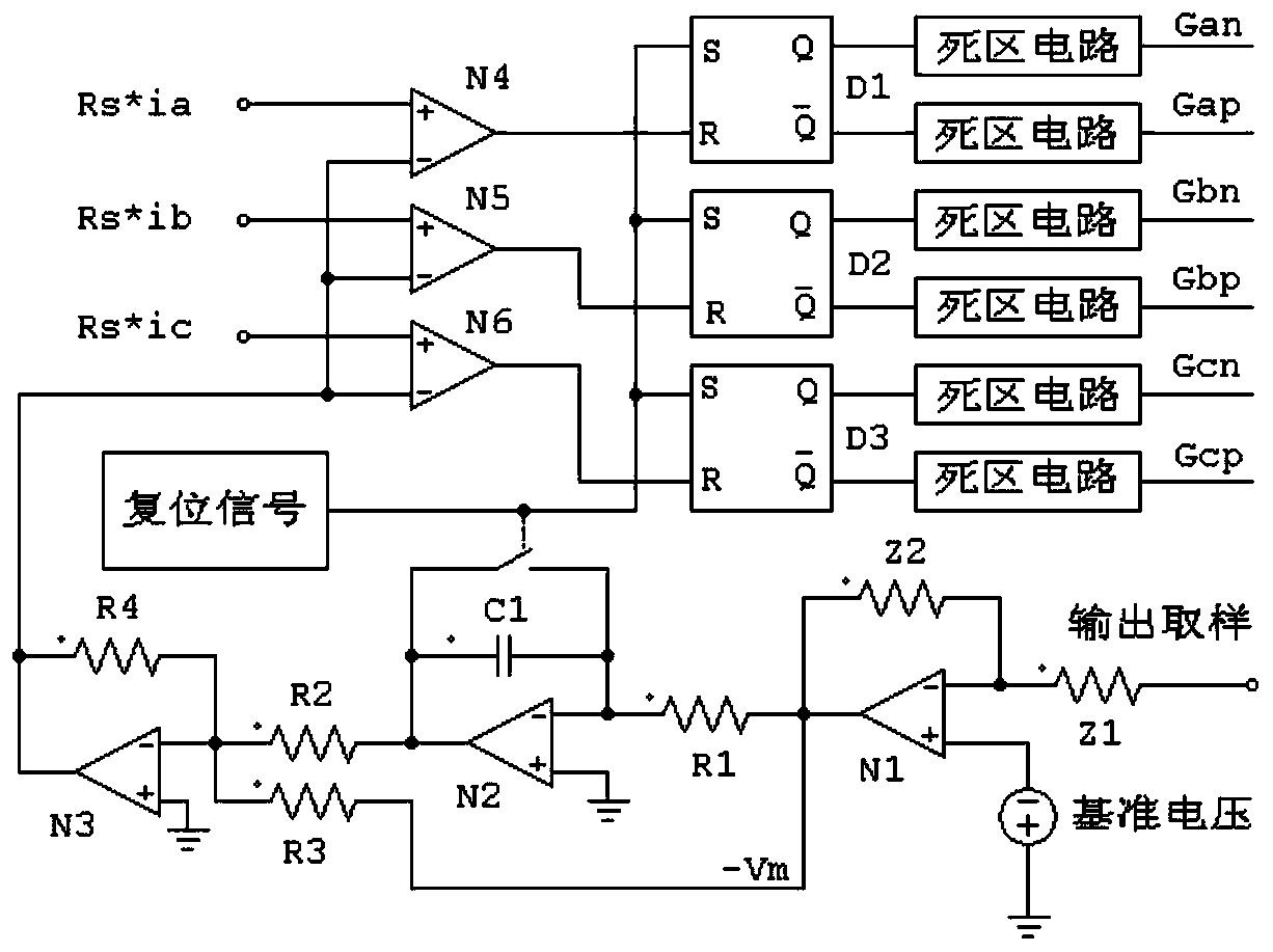
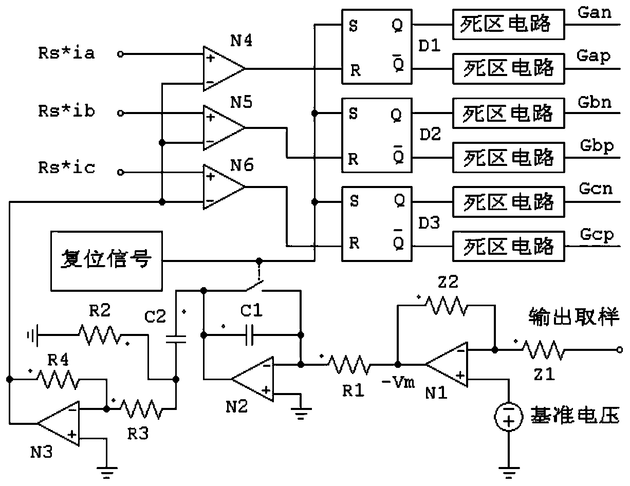
[0034] figure 1 It is a schematic block diagram of the principle circuit of the three-phase six-switch power factor correction main circuit. A single-cycle three-phase six-switch power factor correction PWM modulator according to an embodiment of the present invention, such as image 3 shown. Including: error amplifier, integrator, reset clock signal generator, capacitive coupling DC blockin...


PUM


Abstract

The invention discloses a single-cycle three-phase six-switch power factor correction PWM modulator which comprises an error amplifier, an integrator, a reset clock signal generator, a capacitive coupling blocking circuit, a reverse amplifier and a PWM modulation circuit, wherein a reference voltage and a sampling voltage are respectively input into two input ends of the error amplifier; the output end of the error amplifier is connected with the inverting input end of the integrator, the reset end of the integrator is connected with the output end of the reset clock signal generator, the output end of the integrator is connected with the capacitive coupling blocking circuit, the output end of the capacitive coupling blocking circuit is connected with the inverting input end of the inverting amplifier, and the non-inverting input end of the inverting amplifier is grounded. And different input ends of the PWM modulation circuit respectively input the output voltage, the three-phase input and the reset clock signal of the reverse amplifier, and output a PWM driving signal. According to the invention, the integral parameter tau of the integrator does not need to be strictly matched with the working frequency, and the influence of the temperature characteristic of the component can be eliminated.

Description

technical field [0001] The invention belongs to the technical field of AC-DC converters of electric energy conversion devices, and more specifically relates to a single-cycle three-phase six-switch power factor correction PWM modulator. Background technique [0002] With the wide application of power electronic technology, the hazards of grid harmonic pollution have attracted more and more attention. The harmonics generated by equipment connected to the grid have greatly endangered the safety of the grid. Other equipment cannot work normally, or even cause equipment damage. These serious consequences force people to have higher and higher requirements for the total harmonic distortion (THD) of the input current of the power conversion device and the input power factor (PF). Therefore, the power factor correction of electrical equipment has always been a topic of great concern in the industry, and will definitely pay more and more attention in the future. In the power factor...

Claims


Application Information

Patent Timeline
IPC IPC(8): H02M1/42H02M1/38H02M7/219
CPCH02M1/38H02M1/4216H02M7/219Y02B70/10
Inventor 林杰张黎明张惠军谢波沈鹏程刘克力王飞龙
Owner WUHAN YONGLI TECH CO LTD
Why Eureka
Try Eureka