Defrosting method for air conditioner

A technology of air conditioning and defrosting time, applied in the direction of damage protection, refrigeration safety arrangements, refrigeration components, etc., can solve the problems of poor heating effect, insufficient heat exchanger capacity, and non-energy saving

Active Publication Date: 2013-06-12
QINGDAO HISENSE HITACHI AIR CONDITIONING SYST
View PDF5 Cites 2 Cited by
  • Summary
  • Abstract
  • Description
  • Claims
  • Application Information

AI Technical Summary

Problems solved by technology

This defrosting control method has fixed conditions and parameters for judging whether to enter defrosting, and has the disadvantage that it cannot reasonably adjust the heating operation time.
The defrosting control method is generally set according to the maximum defrosting amount. When there is less frosting, the defrosting will still be carried out according to the established method, so that the capacity of the heat exchanger cannot be fully utilized, resulting in the heating effect of the entire air conditioning system running. Deterioration, neither energy saving nor environmental protection

Method used


Image

  • Defrosting method for air conditioner
  • Defrosting method for air conditioner

Examples


Embodiment 1

[0026] Control method of the present invention is as follows:

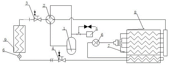
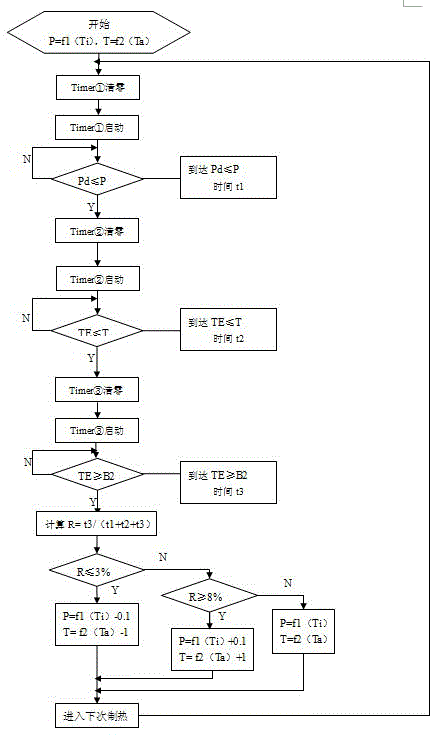
[0027] When the air conditioner unit is turned into the heating state, the four-way valve reversing starts timing, and the high pressure of the system is recorded by the high pressure sensor; when the high pressure Pd≤f1(Ti)MPa, the system has been running for t1 before turning The defrosting temperature sensor is used to record the coil temperature TE of the outdoor heat exchanger. When TE≤f2(Ta)℃, defrosting will start after running time t2. During defrosting, the four-way valve changes direction and starts counting, and turns to the defrosting temperature sensor to record the coil temperature TE of the outdoor heat exchanger. When TE≥12°C, exit defrosting. The running time in defrosting is t3, and turn to the next step. A heating cycle. The ratio of defrosting time to a complete heating cycle time R=t3 / (t1+t2+t3). R≤3%, it can be judged that there is little frost on the outdoor heat exchanger this time, and t...

Embodiment 2

[0031] The difference between this embodiment and Embodiment 1 is that the A value of this embodiment is set to 2.5%, the B value is set to 7.5%, the set value 1 is set to 0.2 MPa, the set value 2 is set to 2 degrees Celsius, and the B2 setting is 10 degrees Celsius.

Embodiment 3

[0033] The difference between this embodiment and Embodiment 1 is that the A value of this embodiment is set to 2%, the B value is set to 7%, the set value 1 is set to 0.3 MPa, the set value 2 is set to 3 degrees Celsius, and B2 is set to is 8 degrees Celsius.


PUM


Abstract

The invention relates to an indoor unit of an air conditioner, in particular to an indoor unit heat exchange structure, and the indoor unit provided with the heat exchange structure. The invention provides the indoor unit heat exchange structure provided with a regenerative branch circuit, and the indoor unit provided with the heat exchange structure. The indoor unit heat exchange structure comprises a heat exchanger provided with a refrigerant side and a water path side; the refrigerant side and the water path side exchange heat in the heat exchanger; the refrigerant side comprises a filter, an electronic expansion valve, a liquid side stop valve and a gas side stop valve which are connected in turn to form a loop; a refrigerating device is arranged between the liquid side stop valve and the gas side stop valve; and the refrigerant side is arranged in the regenerative branch circuit between the gas side and the liquid side. The indoor unit provided with the novel heat exchange structure can increase the supercooling degree of the refrigerant before the electronic expansion valve during refrigeration, can effectively increase the height difference of the indoor unit and an outdoor unit and prolong the effective length of piping, can recover the loss of refrigeration capacity caused by non-uniform refrigerant distribution during refrigeration operation, and improves the refrigerating capacity of a system; and because the refrigerant flowing out of the indoor unit is subjected to regenerative circulation, the superheat degree of the refrigerant flowing out of the indoor unit is increased, a compressor can be effectively prevented from breaking down, and the system reliability is enhanced.

Description

technical field [0001] The invention relates to an air-conditioning system, in particular to an air-conditioning defrosting method. Background technique [0002] The defrosting control methods of most air conditioners only investigate time, temperature and other conditions, and enter defrosting after these three conditions are met. In this defrosting control method, the conditions and parameters for judging whether to enter the defrosting are fixed, and there is a disadvantage that the heating operation time cannot be adjusted reasonably. The defrosting control method is generally set according to the maximum defrosting amount. When there is less frosting, the defrosting will still be carried out according to the established method, so that the capacity of the heat exchanger cannot be fully utilized, resulting in the heating effect of the entire air conditioning system running. Deterioration, neither energy saving nor environmental protection. Contents of the invention ...

Claims


Application Information

Patent Timeline
Patent Type & Authority Patents(China)
IPC IPC(8): F25B47/02F25B49/02
Inventor 张文强丛辉李丛来李亚军何明顺
Owner QINGDAO HISENSE HITACHI AIR CONDITIONING SYST
Why Eureka
Try Eureka