Quick-wire power socket

A power socket and fast technology, applied in the directions of circuits, connections, contact parts, etc., can solve the problems of inability to achieve embedded installation, affect the appearance, inconvenient disassembly and assembly, and achieve the effect of simple structure, low cost, and convenient disconnection operation.

Inactive Publication Date: 2011-12-28
黄华道
View PDF4 Cites 4 Cited by
  • Summary
  • Abstract
  • Description
  • Claims
  • Application Information

AI Technical Summary

Problems solved by technology

[0002] The existing power socket includes a base, an upper cover, and a live wire conductor and a neutral wire conductor with a live wire socket and a neutral wire socket respectively. In addition, it is necessary to set up connecting terminals for the live wire conductor and the neutral wire conductor respectively. The connecting terminals generally include a bottom plate, a pressure plate and a pressure screw. There are many components and it is inconvenient to disassemble and assemble.
In addition, the existing power sockets are generally fixed to the wall by screws, and embedded installation cannot be realized when installed on a partition with a thinner thickness, and the holes formed by the screw installation are often not used for reinstallation after the socket is removed, which affects the appearance

Method used


Image

  • Quick-wire power socket
  • Quick-wire power socket
  • Quick-wire power socket

Examples


Embodiment 1

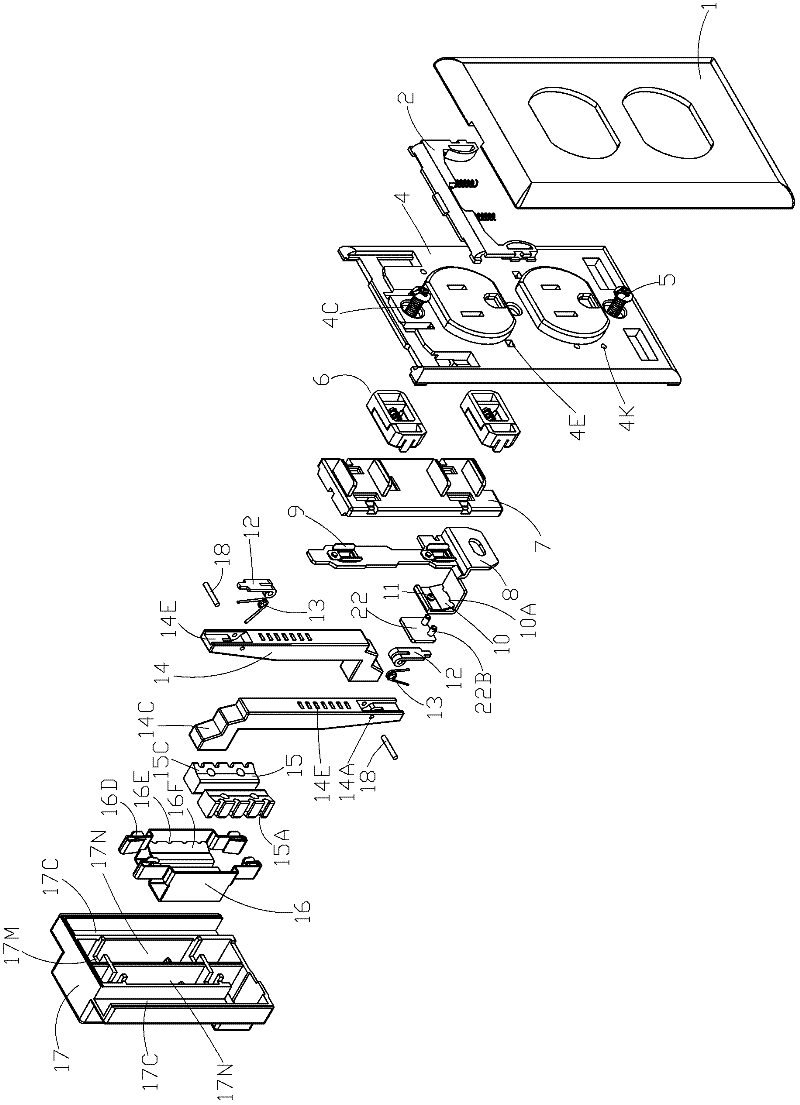
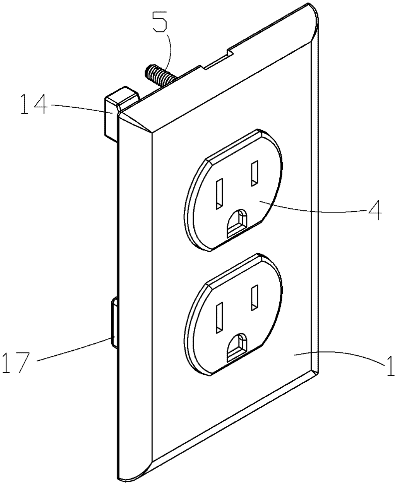
[0049] refer to Figure 1 to Figure 11 , a quick wiring power socket, including a base 17, an upper cover 4 and conductors 16 (including a live conductor and a neutral conductor) with conductive sockets 16D (including live wire sockets and neutral wire sockets), the two conductors are insulated and separated It is arranged in the base 17. In this embodiment, the two conductors are placed in the accommodating groove 17N. The upper cover 4 is provided with jacks corresponding to the positions of the sockets. The live wire conductor and the neutral wire conductor have a side wall and a bottom wall respectively. Both the bottom walls of the two conductors have wiring holes 16B (including wire inlet holes and wire outlet holes), and the bottom wall of the base has corresponding wiring holes 17A (including wire inlet holes and wire outlet holes). The clamping elastic piece 16F with the walls close together, the edge of the clamping elastic piece facing the side wall of the conductor...

Embodiment 2

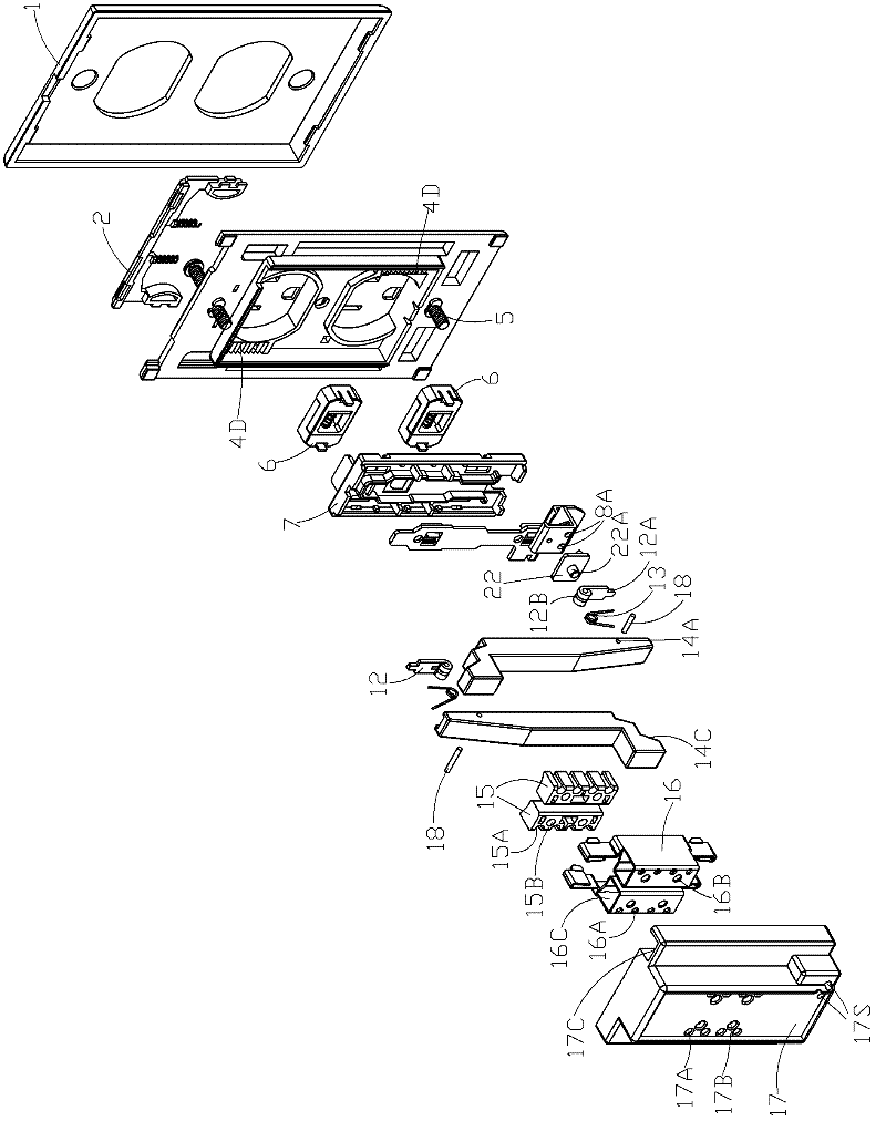
[0062] refer to Figure 12 to Figure 20 , the difference between this embodiment and Embodiment 1 is that the downline insulator 15 is an insulating sheet whose shape is adapted to the bottom wall of the conductor, the insulating sheet is located between the lower surface of the bottom wall of the conductor and the upper surface of the bottom wall of the base, and the bottom wall of the base The bottom wall of the conductor is respectively provided with an off-line through hole corresponding to the position. One side of the insulating sheet has a convex nail 15D corresponding to the off-line through hole on the bottom wall of the base, and the other side has a convex nail corresponding to the off-line through hole on the bottom wall of the conductor. 15C, the clamping elastic piece 16F is in contact with the stud 15C passing through the bottom wall of the conductor so that the stud 15D on the other side of the insulating sheet passes through the bottom wall of the base. Since ...


PUM


Abstract

The invention provides a rapid wiring power socket, comprising a base, an upper cover, a firing line conductor and a zero line conductor, wherein the firing line and zero line conductors are provided with a firing line plug bush and a zero line plug bush respectively; the two conductors are insulated and separated in the base; the upper cover is provided with an insertion hole corresponding to the plug bushes; the firing line conductor and the zero line conductor are provided with a side wall and a bottom wall respectively; the bottom walls of the two conductors are both provided with an incoming line hole and an outgoing line hole; a bottom wall of the base is provided with corresponding incoming line holes and outgoing line holes and fixedly connected with a thread jamming elastic sheetwhich closes up to a side wall from the bottom wall; and clamping gaps which are used for clamping incoming lines and outgoing lines with the side walls of the conductors are arranged on the edges facing to the side walls of the conductors, of the thread jamming elastic sheet. The power socket has the beneficial effects that the structure is simple, the fewer parts are used, the cost is low, and guide lines are inserted into the conductors directly and clamped by the thread jamming elastic sheet so as to realize the wiring operation, thus being rapid and convenient; and a downline insulator is pushed to drive the thread jamming elastic sheet so as to pull out the guide lines, thus the disconnecting operation is convenient extremely.

Description

technical field [0001] The invention relates to a power socket, in particular to a quick wiring power socket which does not need components such as crimping screws to fix the incoming and outgoing wires. Background technique [0002] The existing power socket includes a base, an upper cover, and a live wire conductor and a neutral wire conductor with a live wire socket and a neutral wire socket respectively. In addition, it is necessary to set connection terminals for the live wire conductor and the neutral wire conductor respectively. The connection terminals generally include a base plate, a pressure plate and a pressure screw. There are many components and it is inconvenient to disassemble. In addition, the existing power sockets are generally fixed to the wall by screws, and embedded installation cannot be realized when installed on a partition with a thinner thickness, and the holes formed by the screw installation are often not used for reinstallation after the socket ...

Claims


Application Information

Patent Timeline
Patent Type & Authority Applications(China)
IPC IPC(8): H01R13/02H01R13/502H01R13/73H01R4/48H01R13/652
Inventor 黄华道
Owner 黄华道
Why Eureka
Try Eureka